Nissan Sentra. Manual - part 133


  Index      Nissan     Nissan Sentra (2014 year) - Service and Repair Manual


Search            


Content   ..  131  132  133  134   ..


Nissan Sentra. Manual - part 133


BCS-102

< ECU DIAGNOSIS INFORMATION >

[WITHOUT INTELLIGENT KEY SYSTEM]

BCM

8

(V)

Ground

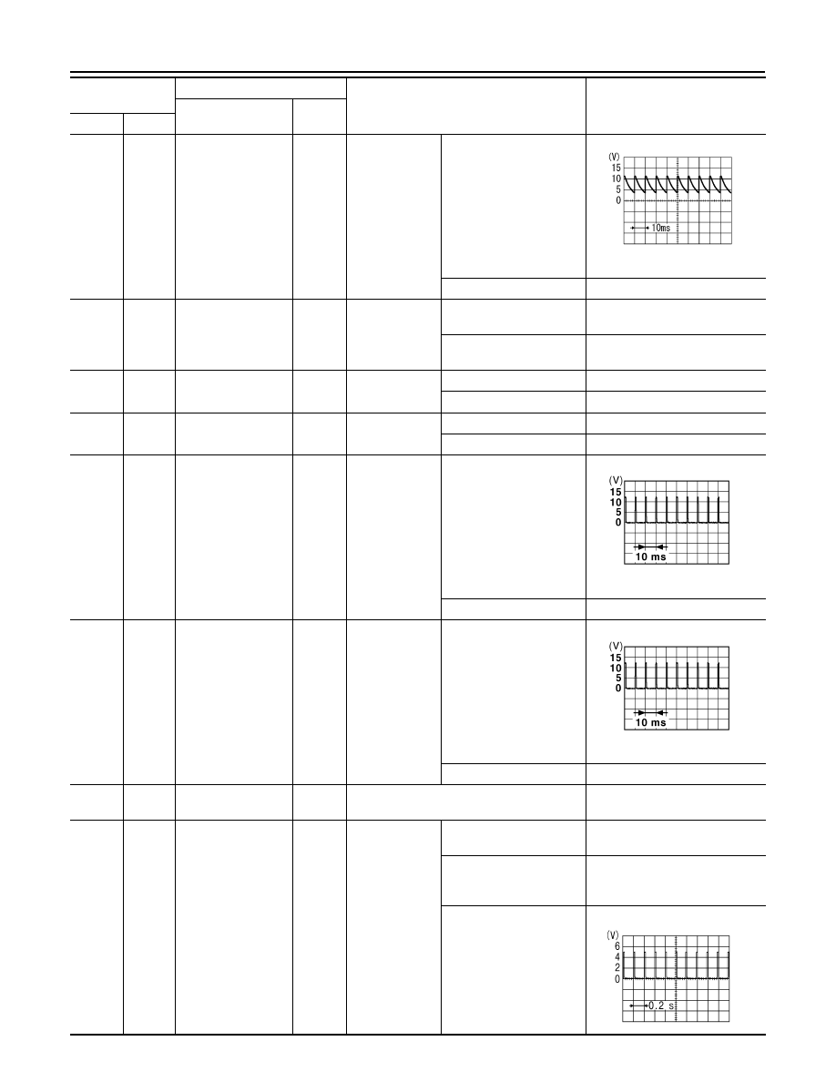
Key cylinder lock sw 
signal

Input

Key cylinder 
switch

N position

7.0 - 8.0 V

LOCK position

0 V

9

(R)

Ground Brake sw signal

Input

Stop lamp 
switch

OFF (brake pedal re-
leased)

0 V

ON (brake pedal de-
pressed)

Battery voltage

10

(W)

Ground

Rear defogger sw 
signal

Input

Rear window 
defogger switch

OFF

Battery voltage

ON

0 V

11

(G)

Ground ACC switch signal 

Input

Ignition switch

OFF

0 V

ACC or ON

Battery voltage

12

(GR)

Ground

Central door lock sw 
signal

Input

Door lock and 
unlock switch

N position

1.0 - 1.5 V

LOCK position

0 V

13

(BR)

Ground

Central door unlock 
sw signal

Input

Door lock and 
unlock switch

N position

1.0 - 1.5 V

UNLOCK position

0 V

18

(V)

Ground Keyless gnd signal

Input

Ignition switch ON

0 V

19

(BR)

Ground

Keyless tuner power 
supply

Input

Ignition switch 
OFF

Key inserted into ignition 
key cylinder

0 V

Key removed from ignition 
key cylinder
(Any door open)

5 V

Key removed from ignition 
key cylinder
(Any door closed)

Terminal No.

(Wire color)

Description

Condition

Value

(Approx.)

Signal name

Input/ 

Output

+

PKIB4960J

JPMIA0012GB

JPMIA0012GB

JPMIA0338JP

BCS

BCM

BCS-103

< ECU DIAGNOSIS INFORMATION >

[WITHOUT INTELLIGENT KEY SYSTEM]

C

D

E

F

G

H

I

J

K

L

B

A

O

P

N

20

(LG)

Ground Keyless tuner signal

Input

Ignition switch 
OFF

Key inserted into ignition 
key cylinder

0 V

Waiting

Signal receiving

21

(P)

Ground

Immobilizer one way 
communication 
(clock) signal

Input/

Output

While waiting

Turn ignition switch ON.

Turn ignition switch ON: Pointer 

of tester should move.

23

(Y)

Ground

Security indicator 
output signal

Input

Security indica-
tor

ON

0 V

Blinking (Ignition switch 
OFF)

11.3 V

OFF

Battery voltage

24

(SB)

Ground

Audio/dongle link 
(serial) signal

Input/

Output

Ignition switch OFF.

5 V

25

(LG)

Ground

Immobilizer two way 
communication sig-
nal

Input/

Output

While waiting

Turn ignition switch ON.

Turn ignition switch ON: Pointer 

of tester should move.

27

(Y)

Ground Air con sw signal

Input

A/C and fan ON 
switch

OFF

Battery voltage

ON

0 V

28

(LG)

Ground Blower fan sw signal

Input

Fan switch

OFF

0 V

I, II, III or IIII

7.0 - 8.0 V

29

(SB)

Ground Hazard sw signal

Input

Hazard switch

OFF

Battery voltage

ON

0 – 1.5 V

Terminal No.

(Wire color)

Description

Condition

Value

(Approx.)

Signal name

Input/ 

Output

+

PIIB7728J

PIIB7729J

JPMIA0014GB

PKIB4960J

BCS-104

< ECU DIAGNOSIS INFORMATION >

[WITHOUT INTELLIGENT KEY SYSTEM]

BCM

30

(L)

Ground

Trunk lid opener 
switch

Input

Trunk lid opener 
switch

Depressed

0 V

Released

1.0 - 1.5 V

32

(LG)

Ground Output 5 signal

Output

Combination 
switch

OFF

7.0 - 8.0 V

FR FOG

1.2 V

Wiper intermittent dial 1

Wiper intermittent dial 2

Wiper intermittent dial 6

Wiper intermittent dial 7

33

(Y)

Ground Output 4 signal

Output

Combination 
switch

OFF

7.0 - 8.0 V

TAIL LAMP

1.2 V

Wiper intermittent dial 1

Wiper intermittent dial 5

Wiper intermittent dial 6

Terminal No.

(Wire color)

Description

Condition

Value

(Approx.)

Signal name

Input/ 

Output

+

JPMIA0012GB

PKIB4960J

PKIB4958J

PKIB4960J

PKIB4958J

BCS

BCM

BCS-105

< ECU DIAGNOSIS INFORMATION >

[WITHOUT INTELLIGENT KEY SYSTEM]

C

D

E

F

G

H

I

J

K

L

B

A

O

P

N

34

(V)

Ground Output 3 signal

Output

Combination 
switch

OFF

7.0 - 8.0 V

HEADLAMP 2

1.2 V

HI BEAM

Wiper intermittent dial 1

Wiper intermittent dial 2

Wiper intermittent dial 3

35

(R)

Ground Output 2 signal

Output

Combination 
switch

OFF

7.0 - 8.0 V

FR WIPER HI

1.2 V

FR WIPER INT
(any intermittent position)

PASSING

HEADLAMP 1

36

(SB)

Ground Output 1 signal

Output

Combination 
switch

OFF

7.0 - 8.0 V

FR WASHER

1.2 V

FR WIPER LOW

TURN LH

TURN RH

Terminal No.

(Wire color)

Description

Condition

Value

(Approx.)

Signal name

Input/ 

Output

+

PKIB4960J

PKIB4958J

PKIB4960J

PKIB4958J

PKIB4960J

PKIB4958J


Content   ..  131  132  133  134   ..