Nissan Sentra. Manual - part 127
BCS-78
< SYSTEM DESCRIPTION >
[WITHOUT INTELLIGENT KEY SYSTEM]
COMPONENT PARTS
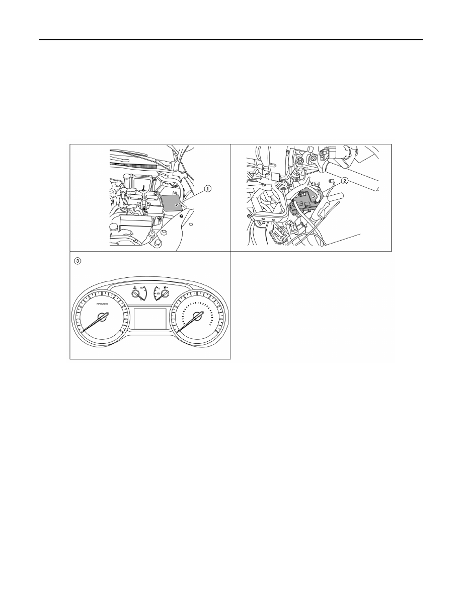
POWER CONSUMPTION CONTROL SYSTEM
POWER CONSUMPTION CONTROL SYSTEM : Component Parts Location
INFOID:0000000009757354
1.
BCM (view with combination meter
removed)
2.
Combination switch (lighting and
turn signal) (with fog lamps)
3.
Combination switch (lighting and
turn signal) (without fog lamps)
4.
Combination switch (wiper and
washer)
1
IPDM E/R
2
BCM (view with instrument panel re-
moved)
3
Combination meter
AWMIA1357ZZ