Nissan Sentra. Manual - part 125


  Index      Nissan     Nissan Sentra (2014 year) - Service and Repair Manual


Search            


Content   ..  123  124  125  126   ..


Nissan Sentra. Manual - part 125


BCS-70

< DTC/CIRCUIT DIAGNOSIS >

[WITH INTELLIGENT KEY SYSTEM]

COMBINATION SWITCH OUTPUT CIRCUIT

COMBINATION SWITCH OUTPUT CIRCUIT

Diagnosis Procedure

INFOID:0000000009757346

Regarding Wiring Diagram information, refer to 

BCS-51, "Wiring Diagram"

.

1.

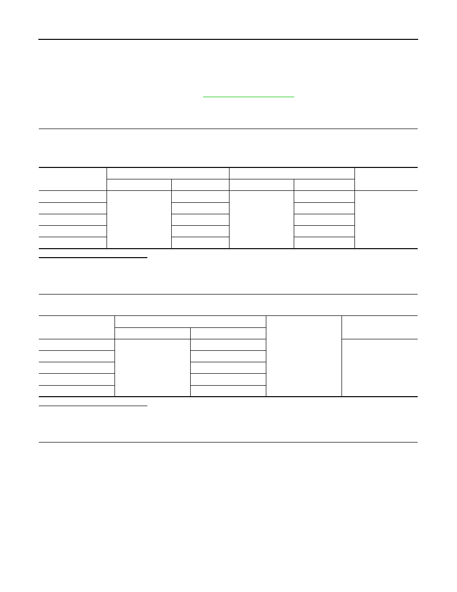
CHECK OUTPUT 1 - 5 CIRCUIT FOR OPEN

1. Turn ignition switch OFF.

2. Disconnect BCM and combination switch connectors.

3. Check continuity between BCM connector and combination switch connector.

Is the inspection result normal?

YES

>> GO TO 2.

NO

>> Repair harness or connectors.

2.

CHECK OUTPUT 1 - 5 CIRCUIT FOR SHORT

Check for continuity between BCM connector and ground.

Is the inspection result normal?

YES

>> Repair harness or connectors.

NO

>> GO TO 3.

3.

CHECK BCM INPUT SIGNAL

1. Connect BCM and combination switch connectors.

2. Turn ON any switch in the system that is malfunctioning.

3. Check voltage between BCM connector and ground.

Combination switch 

signal

BCM

Combination switch

Continuity

Connector

Terminal

Connector

Terminal

OUTPUT 1

M84

6

M28

12

Yes

OUTPUT 2

5

14

OUTPUT 3

4

5

OUTPUT 4

3

2

OUTPUT 5

2

8

Combination switch

signal

BCM

Ground

Continuity

Connector

Terminal

OUTPUT 1

M84

6

No

OUTPUT 2

5

OUTPUT 3

4

OUTPUT 4

3

OUTPUT 5

2

BCS

COMBINATION SWITCH OUTPUT CIRCUIT

BCS-71

< DTC/CIRCUIT DIAGNOSIS >

[WITH INTELLIGENT KEY SYSTEM]

C

D

E

F

G

H

I

J

K

L

B

A

O

P

N

Is the inspection result normal?

Yes

>> Replace BCM. Refer to 

BCS-73, "Removal and Installation"

.

No

>> Replace combination switch.

BCM signal

Terminals

Voltage

(+)

(

−)

BCM

Ground

Connector

Terminal

INPUT 1

M84

6

Refer to 

BCS-29, "Refer-

ence Value"

.

INPUT 2

5

INPUT 3

4

INPUT 4

3

INPUT 5

2

BCS-72

< SYMPTOM DIAGNOSIS >

[WITH INTELLIGENT KEY SYSTEM]

COMBINATION SWITCH SYSTEM SYMPTOMS

SYMPTOM DIAGNOSIS

COMBINATION SWITCH SYSTEM SYMPTOMS

Symptom Table

INFOID:0000000009757347

1. Perform the data monitor of CONSULT to check for any malfunctioning item.
2. Check the malfunction combinations.

Malfunction item: 

×

3. Identify the malfunctioning part from the agreed combination and repair or replace the part.

Malfunction combination

Data monitor item

FR WI

PER HI

FR WIP

ER LOW

F

R

 W

A

SH

ER

 S

W

FR WI

PER INT

INT VOL

U

ME

TURN SIG

NAL R

TURN SIGNAL L

TA

IL

 LA

MP 

SW

H

I BEAM SW

HEAD LAMP SW 

1

HEAD LAMP SW 

2

P

ASSI

N

G

 SW

AU

T

O

 LI

GH

T

 S

W

FR F

O

SW

A

×

×

×

×

B

×

×

×

×

C

×

×

×

D

×

×

×

E

×

×

F

×

×

G

×

×

H

×

×

×

I

×

×

×

×

J

×

×

×

×

K

All Items

L

If only one item is detected or the item is not applicable to the combinations A to K 

Malfunction 

combination

Malfunctioning part

Repair or replace

A

Combination switch INPUT 1 circuit

Inspect the combination switch input circuit applicable to the malfunctioning 
part. Refer to 

BCS-68, "Diagnosis Procedure"

.

B

Combination switch INPUT 2 circuit

C

Combination switch INPUT 3 circuit

D

Combination switch INPUT 4 circuit

E

Combination switch INPUT 5 circuit

F

Combination switch OUTPUT 1 circuit

Inspect the combination switch output circuit applicable to the malfunction-
ing part. Refer to 

BCS-70, "Diagnosis Procedure"

.

G

Combination switch OUTPUT 2 circuit

H

Combination switch OUTPUT 3 circuit

I

Combination switch OUTPUT 4 circuit

J

Combination switch OUTPUT 5 circuit

K

BCM

Replace BCM. Refer to 

BCS-73, "Removal and Installation"

.

L

Combination switch

Replace the combination switch.

BCS

BCM

BCS-73

< REMOVAL AND INSTALLATION >

[WITH INTELLIGENT KEY SYSTEM]

C

D

E

F

G

H

I

J

K

L

B

A

O

P

N

REMOVAL AND INSTALLATION

BCM

Removal and Installation

INFOID:0000000009757348

NOTE:

Before replacing BCM, perform “READ CONFIGURATION” to save or print current vehicle specification. Refer

to 

BCS-61, "CONFIGURATION (BCM) : Description"

.

REMOVAL

1. Disconnect the negative battery terminal. Refer to 

PG-52, "Removal and Installation"

.

2. Remove instrument lower panel LH and instrument side finisher LH. Refer to 

IP-21, "Removal and Instal-

lation"

.

3. Remove fuse block (J/B) screws (A) and position (BCM) aside.

4. Remove harness clip (A).

5. Remove the screws (A) from the BCM (1).

6. Disconnect the harness connectors and remove the BCM.

INSTALLATION

Installation is in the reverse order of removal.

CAUTION:

• Perform “CONFIGURATION (BCM)” when replacing BCM. Refer to 

BCS-61, "CONFIGURATION (BCM)

: Description"

JMMIA1224ZZ

JMMIA1225ZZ

JMMIA1226ZZ


Content   ..  123  124  125  126   ..