Nissan Sentra. Manual - part 99


  Index      Nissan     Nissan Sentra (2014 year) - Service and Repair Manual


Search            


Content   ..  97  98  99  100   ..


Nissan Sentra. Manual - part 99


AV-388

< DTC/CIRCUIT DIAGNOSIS >

[NAVIGATION WITH BOSE]

MICROPHONE SIGNAL CIRCUIT

Is the inspection result normal?

YES

>> Replace AV control unit. Refer to 

AV-406, "Removal and Installation"

.

NO

>> Replace microphone. Refer to 

AV-421, "Removal and Installation"

.

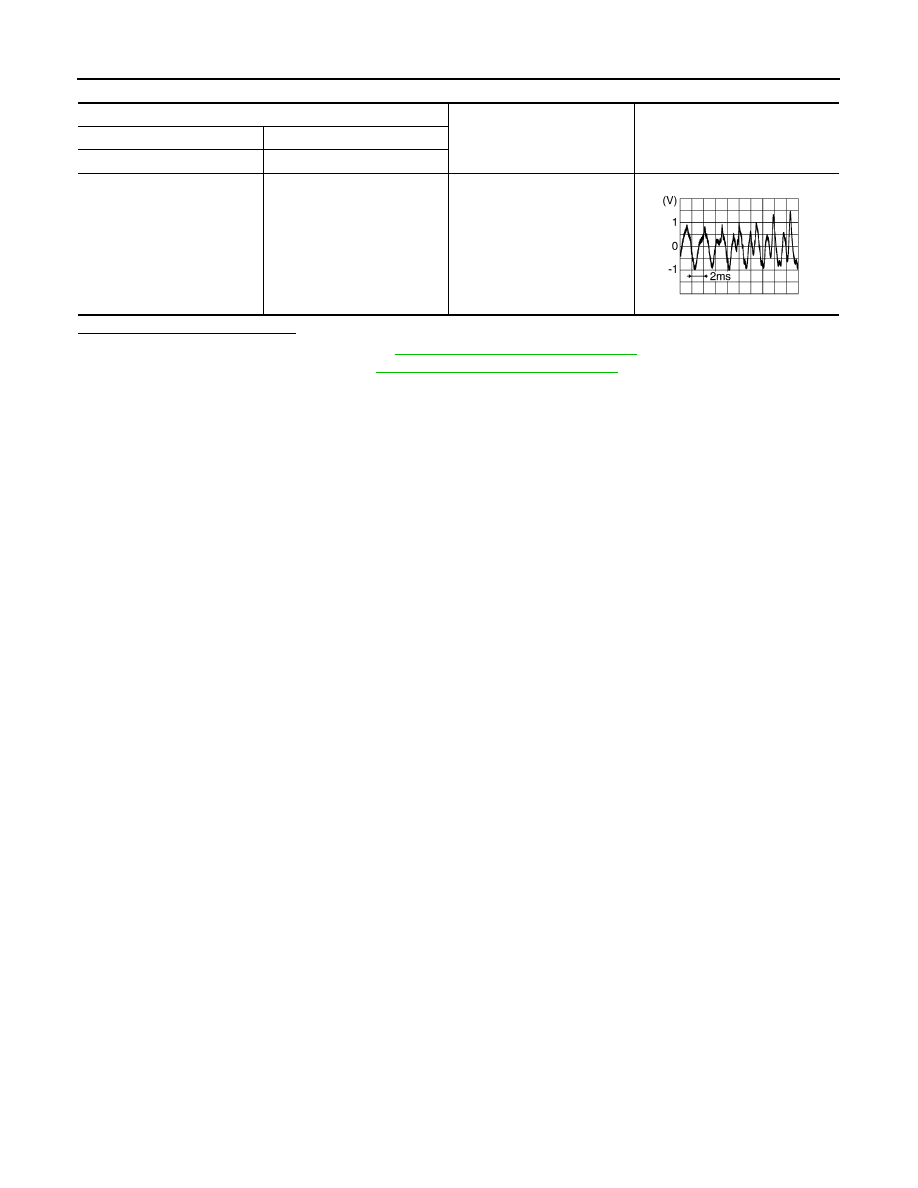
AV control unit connector M101

Condition

Reference value

(+)

(

−)

Terminal

Terminal

43

41

Speak into microphone.

SKIB3609E

AV

STEERING SWITCH

AV-389

< DTC/CIRCUIT DIAGNOSIS >

[NAVIGATION WITH BOSE]

C

D

E

F

G

H

I

J

K

L

M

B

A

O

P

STEERING SWITCH

Diagnosis Procedure

INFOID:0000000009759059

Regarding Wiring Diagram information, refer to 

AV-331, "Wiring Diagram"

.

1.

CHECK STEERING WHEEL AUDIO CONTROL SWITCH RESISTANCE

1. Turn ignition switch OFF.

2. Disconnect combination switch (spiral cable) connector M79.

3. Check resistance between the terminals of combination switch (spiral cable) connector M79.

Is the inspection result normal?

YES

>> GO TO 2.

NO

>> Replace steering switches. Refer to 

AV-411, "Removal and Installation"

.

2.

CHECK COMBINATION SWITCH (SPIRAL CABLE)

Check continuity between combination switch (spiral cable) connectors M79 and M80.

Is the inspection result normal?

YES

>> GO TO 3.

NO

>> Replace combination switch (spiral cable). Refer to 

SR-16, "Removal and Installation"

.

3.

CHECK HARNESS BETWEEN COMBINATION SWITCH (SPIRAL CABLE) AND AV CONTROL UINT 

1. Disconnect AV control unit connector M100.

2. Check continuity between combination switch (spiral cable) connector M80 and AV control unit connector

M100.

Combination switch (spiral cable) connector M79

Condition

Resistance 

(Approx.)

Terminal

Terminal

14

17

Depress SOURCE switch.

1

Depress  

switch.

121

Depress  

switch.

321

Depress  

switch.

723

15

Depress  

switch.

1

Depress  

switch.

121

Depress  

switch. 

321

Combination switch (spiral cable) 

Continuity

Connector

Terminal

Connector

Terminal

M79

14

M80

24

Yes

15

31

17

33

Combination switch (spiral cable)

AV control unit 

Continuity

Connector

Terminal

Connector

Terminal

M80

24

M100

6

Yes

31

16

33

15

AV-390

< DTC/CIRCUIT DIAGNOSIS >

[NAVIGATION WITH BOSE]

STEERING SWITCH

3. Check continuity between combination switch (spiral cable) connector M80 and ground.

Is the inspection result normal?

YES

>> Replace AV control unit. Refer to 

AV-406, "Removal and Installation"

.

NO

>> Repair or replace harness or connectors.

Combination switch (spiral cable)

Ground

Continuity

Connector

Terminal

M80

24

No

31

33

AV

USB CONNECTOR

AV-391

< DTC/CIRCUIT DIAGNOSIS >

[NAVIGATION WITH BOSE]

C

D

E

F

G

H

I

J

K

L

M

B

A

O

P

USB CONNECTOR

Diagnosis Procedure

INFOID:0000000009759060

Regarding Wiring Diagram information, refer to 

AV-331, "Wiring Diagram"

.

1.

CHECK USB INTERFACE HARNESS CONTINUITY

1. Turn ignition switch OFF.

2. Disconnect AV control unit connector M114 and USB interface connector M132.

3. Check continuity between AV control unit connector M114 and USB interface connector M132.

4. Check continuity between AV control unit connector M131 and ground.

Is the inspection result normal?

YES

>> Replace the USB interface. Refer to 

AV-416, "Removal and Installation"

.

NO

>> Repair or replace harness or connectors.

AV control unit

USB interface 

Continuity

Connector

Terminal

Connector

Terminal

M114

45

M132

2

Yes

46

1

47

4

48

3

49

5

AV control unit

Continuity

Connector

Terminal

M114

45

Ground

No

47


Content   ..  97  98  99  100   ..