Nissan Sentra. Manual - part 22


  Index      Nissan     Nissan Sentra (2014 year) - Service and Repair Manual


Search            


Content   ..  20  21  22  23   ..


Nissan Sentra. Manual - part 22


AV-80

< SYSTEM DESCRIPTION >

[DISPLAY AUDIO WITHOUT BOSE]

DIAGNOSIS SYSTEM (AUDIO UNIT)

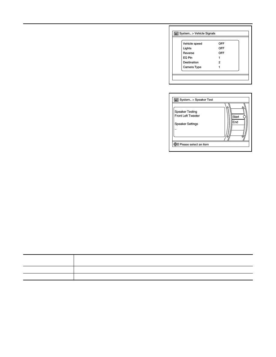
A comparison check can be made of each actual vehicle signal and

the signals recognized by the system.

Speaker Test

Select Speaker Test to display the Speaker Diagnosis screen. Press

Start to generate a test tone in a speaker. Press Start again to gener-

ate a test tone in the next speaker. Press End to stop the test tones.

Error History

The self diagnosis results are judged depending on whether any error occurs from when Self Diagnosis is

selected until the self diagnosis results are displayed.

However, the diagnosis results are judged normal if an error has occurred before the ignition switch is turned

ON and then no error has occurred until the self diagnosis start. Check the Error Record to detect any error

that may have occurred before the self diagnosis start because of this situation.

The frequency of occurrence is displayed in a count up manner. The actual count up method differs depending

on the error item. 

Count up method A

• The counter is set to 40 if an error occurs. 1 is subtracted from the counter if the condition is normal at a next

ignition ON cycle. 

• The counter lower limit is 1. The counter can be reset (no error record display) with the Delete log switch.

Count up method B

• The counter increases by 1 if an error occurs when ignition switch is ON. The counter will not decrease even

if the condition is normal at the next ignition ON cycle. 

• The counter upper limit is 50. Any counts exceeding 50 are ignored. The counter can be reset (no error

record display) with the Delete log switch.

Error item

Some error items may be displayed simultaneously according to the cause. If some error items are displayed

simultaneously, the detection of the cause can be performed by the combination of display items

AWNIA2633GB

AWNIA2634GB

Display type of occurrence 

frequency

Error history display item

Count up method A

AV communication line, control unit (AV)

Count up method B

Other than the above

AV

DIAGNOSIS SYSTEM (AUDIO UNIT)

AV-81

< SYSTEM DESCRIPTION >

[DISPLAY AUDIO WITHOUT BOSE]

C

D

E

F

G

H

I

J

K

L

M

B

A

O

P

AV COMM Diagnosis

• Displays the communication status between audio unit (master

unit) and Bluetooth

®

 control unit.

• The error counter displays OK if any malfunction was not detected

in the past and displays 0 if a malfunction is detected. It increases

by 1 if the condition is normal at the next ignition switch ON cycle.

The upper limit of the counter is 39.

• The error counter is erased if Reset is pressed.

NOTE:

“???” indicates UNKWN.

Delete Unit Connection Log

Deletes any unit connection records and error records from the

audio unit memory (clears the records of the unit that has been

removed).

Initialize Settings

Deletes data stored from the audio unit.

Error item

Description

Possible cause

CONTROL UNIT (AV)

AV communication circuit initial diagnosis 
malfunction is detected.

Replace the audio unit if the malfunction 
occurs constantly.
Refer to 

AV-122, "Removal and Installation"

AV COMM CIRCUIT

When one of the following is detected:
• malfunction is detected in Bluetooth

®


control unit power supply and ground cir-
cuits.

• malfunction is detected in AV communi-

cation circuits between audio unit and 
Bluetooth

®

 control unit.

• Bluetooth

®

 control unit power supply or 

ground circuits.
Refer to 

AV-101, "BLUETOOTH® CON-

TROL UNIT : Diagnosis Procedure"

.

• AV communication circuits between au-

dio unit and Bluetooth

®

 control unit.

Items

Status

(Current)

Counter

(Past)

BUS OFF

OK / ???

OK / 0 – 39

C Rx(BTHF-H/U)

OK / ???

OK / 0 – 39

AWNIA2833GB

AWNIA2637GB

JSNIA0155GB

AV-82

< SYSTEM DESCRIPTION >

[DISPLAY AUDIO WITHOUT BOSE]

DIAGNOSIS SYSTEM (BLUETOOTH® CONTROL UNIT)

DIAGNOSIS SYSTEM (BLUETOOTH® CONTROL UNIT)

Diagnosis Description

INFOID:0000000009758845

The Bluetooth

®

 control unit has two diagnostic checks. The first diagnostic check is performed automatically

every ignition cycle during control unit initialization. The second diagnostic check is performed by the techni-

cian using the steering wheel audio control switches prior to trouble diagnosis.

Bluetooth

®

 CONTROL UNIT INITIALIZATION CHECKS

• Internal control unit failure
• Bluetooth

®

 antenna connection open or shorted

• Steering wheel audio control switches [

 (PHONE/SEND),   (PHONE/END)] stuck closed

• Vehicle speed pulse count

• Microphone connection test (with playback to operator)
• Bluetooth

®

 inquiry check

OPERATION PROCEDURE

1. Turn ignition switch to ACC or ON.
2. Wait for the Bluetooth

®

 system to complete initialization. This may take up to 20 seconds.

3. Press and hold the steering wheel audio control switch 

(PHONE/SEND) button for at least 5 seconds. The Bluetooth

®

system will begin to play a verbal prompt.

4. While the prompt is playing, press and hold the steering wheel

audio control switch 

 (PHONE/END) button until you hear the

“Diagnostics mode” prompt. The Bluetooth

®

 system will sound a

5-second beep.

5. While the beep is sounding, press and hold the steering wheel

audio control switch 

 (PHONE/END) button again until you

hear prompts.

6. The Bluetooth

®

 system has now entered into the diagnostic

mode. Results of the diagnostic checks will be verbalized to the

technician. Refer to 

AV-82, "Work Flow"

.

7. After the failure records are reported, an interactive microphone

test will be performed. Follow the voice prompt. If the micro-

phone test fails, refer to 

AV-82, "Work Flow"

.

Work Flow

INFOID:0000000009758846

AWNIA2834ZZ

AWNIA2835ZZ

Failure Message

Action

“Internal failure”

Replace Bluetooth

®

 control unit. Refer to 

AV-134, "Removal and Installation"

“Bluetooth

®

 antenna open”

1.

Inspect harness connection.

2.

Replace Bluetooth

®

 antenna. Refer to 

AV-134, "Removal and Installation"

.

“Bluetooth

®

 antenna shorted”

“Phone/Send for Hands Free System is stuck”

Check steering wheel audio control switches. Refer to 

AV-114, "Diagnosis Proce-

dure"

.

“Phone/End for the Hands Free System is stuck”

“Microphone test” (failed interactive test)

1.

Inspect harness between Bluetooth

®

 control unit and microphone.

2.

Replace microphone. Refer to 

AV-135, "Removal and Installation"

 .

AV

AUDIO UNIT

AV-83

< ECU DIAGNOSIS INFORMATION >

[DISPLAY AUDIO WITHOUT BOSE]

C

D

E

F

G

H

I

J

K

L

M

B

A

O

P

ECU DIAGNOSIS INFORMATION

AUDIO UNIT

Reference Value

INFOID:0000000009758847

TERMINAL LAYOUT

PHYSICAL VALUES

AWNIA2820ZZ

Terminal

(Wire color)

Description

Condition

Reference value

(Approx.)

+

Signal name

Input/

Output

Ignition 

switch

Operation

2

(L)

3

(P)

Sound signal front speaker 
LH

Output

ON

Sound output

4

(LG)

5

(W)

Sound signal rear speaker 
LH

Output

ON

Sound output

6

(G)

15

(P)

Steering switch signal A

Input

Ignition 

switch 

ON

Press SOURCE switch

 0V

Press  

switch

1.0V

Press  

switch

2.0V

Press  

switch

3.0V

Except above

5.0V

7

(P)

Ground ACC power supply

Input

ACC

Battery voltage

9

 (R)

8

(GR)

Illumination control signal

Input

ON

Headlamps ON

Battery voltage

SKIB3609E

SKIB3609E


Content   ..  20  21  22  23   ..