Nissan Sentra. Manual - part 7
 

  Index      Nissan     Nissan Sentra (2014 year) - Service and Repair Manual


Search            


Content   ..  5  6  7  8   ..


Nissan Sentra. Manual - part 7


AV-20

< ECU DIAGNOSIS INFORMATION >

[BASE AUDIO]

AUDIO UNIT

ECU DIAGNOSIS INFORMATION

AUDIO UNIT

Reference Value

INFOID:0000000009758806

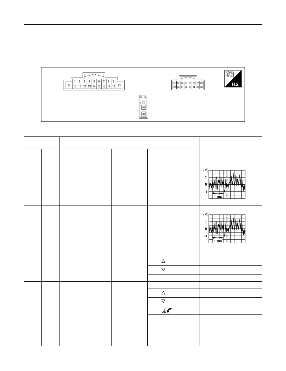
TERMINAL LAYOUT

PHYSICAL VALUES

AWNIA3359ZZ

Terminal

 (Wire color)

Description

Condition

Reference value

(Approx.)

+

Signal name

Input/

Output

Ignition 

switch

Operation

(L)

3

 (P)

Sound signal front speaker 
LH

Output

ON

Sound output

(LG)

(W)

Sound signal rear speaker 
LH

Output

ON

Sound output

6

1

(G)

15

1

(V)

Steering switch signal A

Input

Ignition 

switch 

ON

Press SOURCE switch

 0V

Press  

switch

1.0V

Press  

switch

2.0V

Except above

5.0V

6

2

(G)

15

2

(P)

Steering switch signal A

Input

Ignition 

switch 

ON

Press SOURCE switch

 0V

Press  

switch

1.0V

Press  

switch

2.0V

Press  

switch

3.0V

Except above

5.0V

7

 (P)

Ground

ACC power supply

Input

ACC

Ignition switch ACC or ON

Battery voltage

9

 (R)

8

(GR)

Illumination control signal

Input

ON

Headlamps ON

Battery voltage

SKIA0177E

SKIA0177E

AV

AUDIO UNIT

AV-21

< ECU DIAGNOSIS INFORMATION >

[BASE AUDIO]

C

D

E

F

G

H

I

J

K

L

M

B

A

O

P

11 

(SB)

12 

(V)

Sound signal front speaker 
RH

Output

ON

Sound output

13

 (BR)

14

 (Y)

Sound signal rear speaker 
RH

Output

ON

Sound output

16

1

(R)

15

1

(V)

Steering switch signal B

Input

Ignition 

switch 

ON

Press  

switch

0V

Press  

switch

1.0V

Except above

5.0V

16

2

(LG)

15

2

(P)

Steering switch signal B

Input

Ignition 

switch 

ON

Press  

switch

0V

Press  

switch

1.0V

Press  

switch

2.0V

Except above

5.0V

18

(Y)

Ground Vehicle speed signal

Input

ON

When vehicle speed is ap-
prox. 40 km/h (25 MPH).

19 

(Y)

Ground

Battery power supply

Input

Battery voltage

23

(B)

Ground EQ03 Ground

Ignition switch ON 

0 V

27

(SB)

M CAN1-H

Input/

Output

28

(LG)

M CAN1-L

Input/

Output

29

(Y)

Ground TEL ON

Output

ON

30

Shield

32

(BR)

31

(GR)

TEL voice signal

Input

Ignition 

switch 

ON

During voice guide output 
with  

switch 

pressed.

Terminal

 (Wire color)

Description

Condition

Reference value

(Approx.)

+

Signal name

Input/

Output

Ignition 

switch

Operation

SKIA0177E

SKIA0177E

JSNIA0012GB

SKIB3609E

AV-22

< ECU DIAGNOSIS INFORMATION >

[BASE AUDIO]

AUDIO UNIT

1

: without Bluetooth

®

2

: with Bluetooth

®

35

(B)

M CAN2-H

Input/

Output

36

(R)

M CAN2-L

Input/

Output

37

(B)

Ground Antenna amp. ON signal

Output

ON

Battery voltage

38

(B)

Ground AM/FM antenna signal

Input

ON

5.0 V

Terminal

 (Wire color)

Description

Condition

Reference value

(Approx.)

+

Signal name

Input/

Output

Ignition 

switch

Operation

AV

BLUETOOTH® CONTROL UNIT

AV-23

< ECU DIAGNOSIS INFORMATION >

[BASE AUDIO]

C

D

E

F

G

H

I

J

K

L

M

B

A

O

P

BLUETOOTH® CONTROL UNIT

Reference Value

INFOID:0000000009758807

TERMINAL LAYOUT

PHYSICAL VALUES

AWNIA2819ZZ

Terminal

(wire color)

Description

Condition

Reference value

(Approx.)

+

Signal name

Input/out-

put

1

 (Y)

Ground

Battery power

Input

Battery voltage

(W)

Ground

ACC power

Input

Ignition 

switch 

ACC/ON

Battery voltage

(BR)

Ground

 IGN power

Input

Ignition 

switch 

ON/

START

Battery voltage

(B)

Ground

Ground

Ignition 

switch ON

0V

7

 (G)

MIC in signal

Input

(BR)

10 

(GR)

Audio out

Output

Ignition 

switch 

ACC/ON

Bluetooth

®

 control 

unit sends audio sig-

nal

11 

(Y)

Mute control

Output

12

(G)

14

(V)

LAD IN 1

Input

Ignition 

switch ON

Press SOURCE 
switch

 0V

Press  

switch

1.0V

Press  

switch

2.0V

Press  

switch

3.0V

Except above

5.0V

SKIB3609E


Content   ..  5  6  7  8   ..