Nissan Leaf. Manual - part 996
PCS
POWER SWITCH POSITION INDICATOR
PCS-67
< DTC/CIRCUIT DIAGNOSIS >
[POWER DISTRIBUTION SYSTEM]
C
D
E
F
G
H
I
J
K
L
B
A
O
P
N
Is the inspection normal?
YES
>> Replace BCM. Refer to
BCS-72, "Removal and Installation"
NO
>> Replace power switch. Refer to
PCS-71, "Removal and Installation"
.
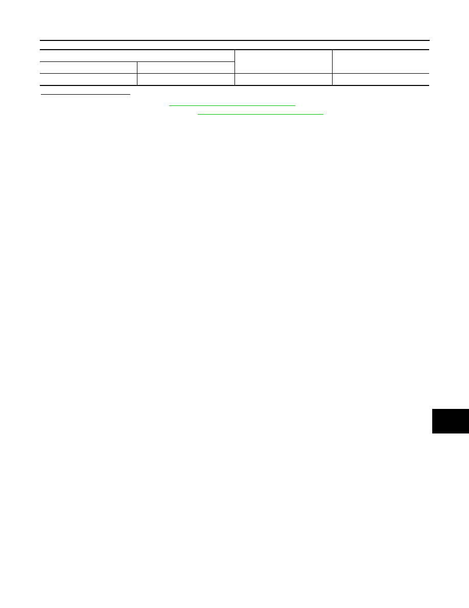
Power switch
Ground
Voltage
(Approx.)
Connector
Terminal
M33
7
—
Battery voltage