Nissan Leaf. Manual - part 970


  Index      Nissan     Nissan Leaf (2011-2014 year) - Service and Repair Manual


Search            


Content   ..  968  969  970  971   ..


Nissan Leaf. Manual - part 970


MWI

U1010 CONTROL UNIT (CAN)

MWI-83

< DTC/CIRCUIT DIAGNOSIS >

C

D

E

F

G

H

I

J

K

L

M

B

A

O

P

U1010 CONTROL UNIT (CAN)

Description

INFOID:0000000010122415

Initial diagnosis of combination meter.

DTC Logic

INFOID:0000000010122416

DTC DETECTION LOGIC

Diagnosis Procedure

INFOID:0000000010122417

1.

REPLACE COMBINATION METER

When DTC “U1010” is detected, replace combination meter. 

>> Replace combination meter. Refer to 

MWI-102, "Removal and Installation"
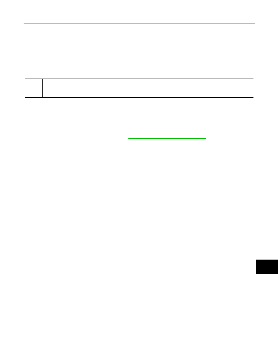
.

DTC

Display contents of CONSULT

Diagnostic item is detected when...

Probable malfunction location

U1010

CONTROL UNIT (CAN)
[U1010]

When detecting error during the initial diagnosis 
of the CAN controller of combination meter.

Combination meter

MWI-84

< DTC/CIRCUIT DIAGNOSIS >

B2205 VEHICLE SPEED

B2205 VEHICLE SPEED

Description

INFOID:0000000010122418

Vehicle speed signal is transmitted from ABS actuator and electric unit (control unit) via CAN communication

to combination meter.

DTC Logic

INFOID:0000000010122419

DTC DETECTION LOGIC

Diagnosis Procedure

INFOID:0000000010122420

1.

PERFORM SELF-DIAGNOSIS OF ABS ACTUATOR AND ELECTRIC UNIT (CONTROL UNIT)

Perform “Self Diagnostic Result” of “ABS”, and repair or replace malfunctioning parts.

>> Refer to 

BRC-46, "CONSULT Function"

.

DTC

Display contents of 

CONSULT

Diagnostic item is detected when...

Probable malfunction location

B2205

VEHICLE SPEED
[B2205]

An abnormal vehicle speed signal is input 
from ABS actuator and electric unit (control 
unit) for 2 seconds or more.

• Wheel sensor
• ABS actuator and electric unit (control unit)

MWI

POWER SUPPLY AND GROUND CIRCUIT

MWI-85

< DTC/CIRCUIT DIAGNOSIS >

C

D

E

F

G

H

I

J

K

L

M

B

A

O

P

POWER SUPPLY AND GROUND CIRCUIT

COMBINATION METER
COMBINATION METER : Diagnosis Procedure

INFOID:0000000010122421

Regarding Wiring Diagram information, refer to 

MWI-68, "Wiring Diagram"

.

1.

CHECK FUSES

Check that the following fuses are not blown:

Is the fuse blown?

YES

>> Replace the blown fuse after repairing the affected circuit.

NO

>> GO TO 2.

2.

CHECK POWER SUPPLY CIRCUIT

Check voltage between combination meter harness connector and ground.

Is the inspection result normal?

YES

>> GO TO 3.

NO

>> Repair or replace harness or connector.

3.

CHECK GROUND CIRCUIT

1. Power switch OFF.

2. Disconnect combination meter connector.

3. Check continuity between combination meter harness connector and ground.

Is the inspection result normal?

YES

>> Inspection End.

NO

>> Repair or replace harness or connector.

UPPER METER
UPPER METER : Diagnosis Procedure

INFOID:0000000010122422

Regarding Wiring Diagram information, refer to 

MWI-68, "Wiring Diagram"

.

Power source

Fuse No.

Battery

11

Power switch ON 

5

Terminals

Power switch position

Voltage

(Approx.)

(+)

(

−)

Combination meter

Ground

Connector

Terminal

M34

1

OFF

Battery voltage

3

ON

Combination meter

Ground

Continuity

Connector

Terminal

M34

5

Yes

6

MWI-86

< DTC/CIRCUIT DIAGNOSIS >

POWER SUPPLY AND GROUND CIRCUIT

1.

CHECK POWER SUPPLY CIRCUIT

Check voltage between upper meter harness connector and ground.

Is the inspection result normal?

YES

>> GO TO 2.

NO

>> Repair or replace harness or connector.

2.

CHECK GROUND CIRCUIT

1. Power switch OFF.

2. Disconnect upper meter connector.

3. Check continuity between upper meter harness connector and ground.

Is the inspection result normal?

YES

>> Inspection End.

NO

>> Repair or replace harness or connector.

Terminals

Power switch position

Voltage

(Approx.)

(+)

(

−)

Upper meter

Ground

Connector

Terminal

M62

1

OFF

Battery voltage

2

ON

Upper meter

Ground

Continuity

Connector

Terminal

M62

6

Yes


Content   ..  968  969  970  971   ..