Index Nissan Nissan Leaf (2011-2014 year) - Service and Repair Manual
Search
Content .. 967 968 969 970 ..
Nissan Leaf. Manual - part 969
MWI
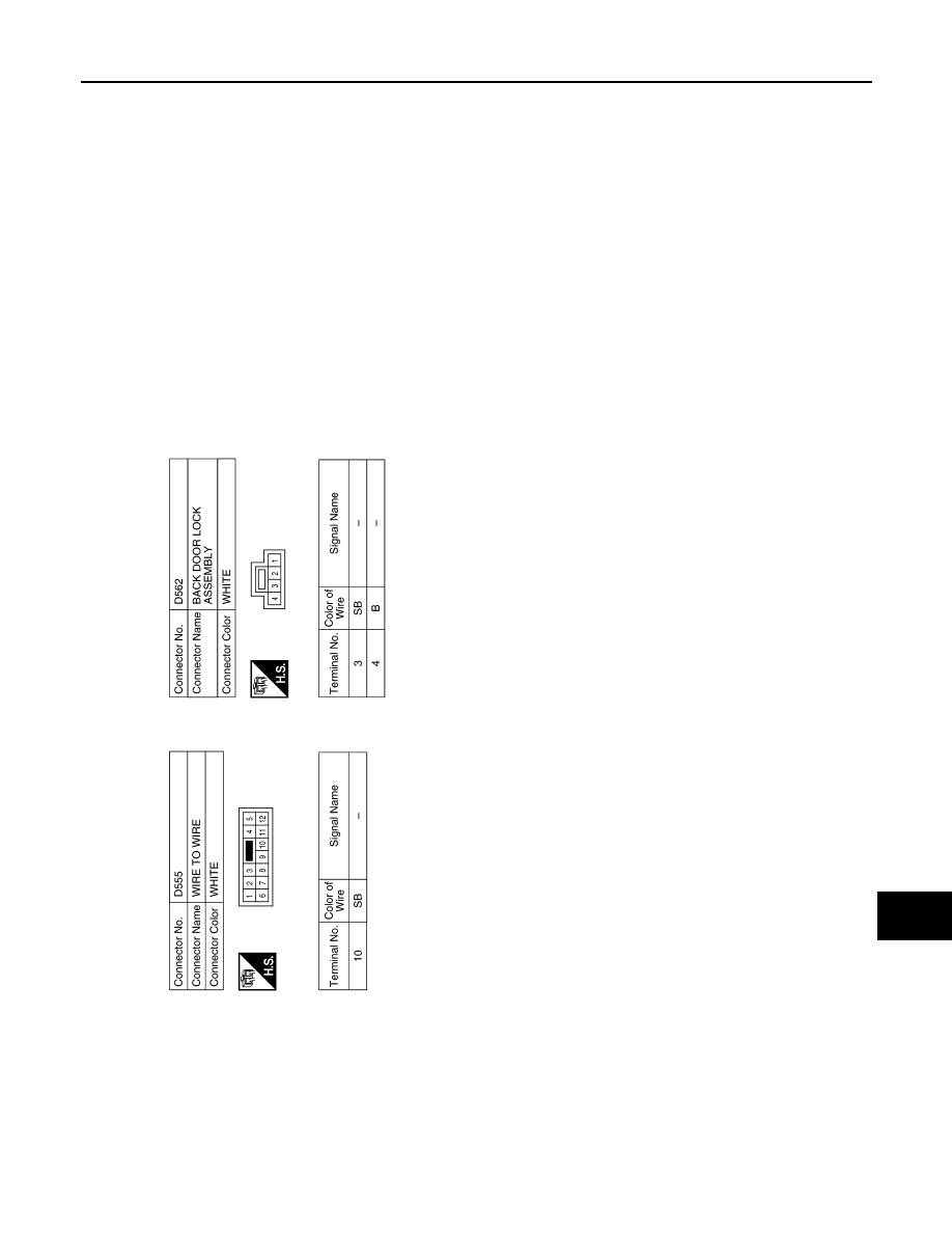
METER SYSTEM
MWI-79
< WIRING DIAGRAM >
C
D
E
F
G
H
I
J
K
L
M
B
A
O
P
AANIA2882GB