Nissan Leaf. Manual - part 902


  Index      Nissan     Nissan Leaf (2011-2014 year) - Service and Repair Manual


Search            


Content   ..  900  901  902  903   ..


Nissan Leaf. Manual - part 902


LAN-70

< DTC/CIRCUIT DIAGNOSIS >

[CAN]

AVM BRANCH LINE CIRCUIT

AVM BRANCH LINE CIRCUIT

Diagnosis Procedure

INFOID:0000000010120391

1.

CHECK CONNECTOR

1. Turn the power switch OFF.

2. Disconnect the 12V battery cable from the negative terminal. Refer to 

LAN-26, "Precautions for Removing

Battery Terminal"

.

3. Check the terminals and connectors of the around view monitor control unit for damage, bend and loose

connection (unit side and connector side).

Is the inspection result normal?

YES

>> GO TO 2.

NO

>> Repair the terminal and connector.

2.

CHECK HARNESS FOR OPEN CIRCUIT

1. Disconnect the connector of around view monitor control unit.

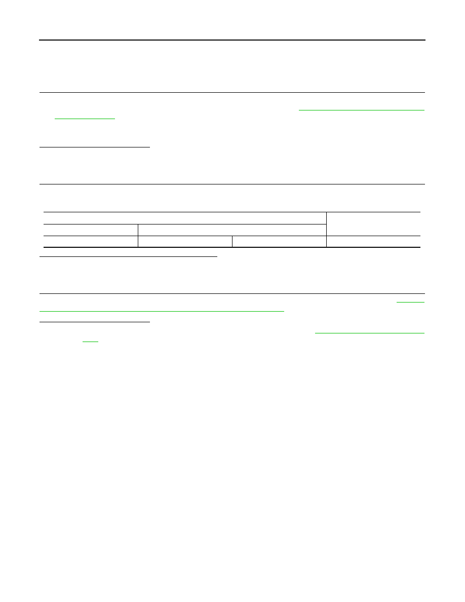
2. Check the resistance between the around view monitor control unit harness connector terminals.

Is the measurement value within the specification?

YES

>> GO TO 3.

NO

>> Repair the around view monitor control unit branch line.

3.

CHECK POWER SUPPLY AND GROUND CIRCUIT

Check the power supply and the ground circuit of the around view monitor control unit. Refer to 

AV-454,

"AROUND VIEW MONITOR CONTROL UNIT : Diagnosis Procedure"

.

Is the inspection result normal?

YES (Present error)>>Replace the around view monitor control unit. Refer to 

AV-502, "Removal and Installa-

tion"

.

YES (Past error)>>Error was detected in the around view monitor control unit branch line.

NO

>> Repair the power supply and the ground circuit.

Around view monitor control unit harness connector

Resistance (

Ω)

Connector No.

Terminal No.

M32

12

10

Approx. 54 – 66

LAN

VSP BRANCH LINE CIRCUIT

LAN-71

< DTC/CIRCUIT DIAGNOSIS >

[CAN]

C

D

E

F

G

H

I

J

K

L

B

A

O

P

N

VSP BRANCH LINE CIRCUIT

Diagnosis Procedure

INFOID:0000000010120392

1.

CHECK CONNECTOR

1. Turn the power switch OFF.

2. Disconnect the 12V battery cable from the negative terminal. Refer to 

LAN-26, "Precautions for Removing

Battery Terminal"

.

3. Check the terminals and connectors of the approaching vehicle sound for pedestrians (VSP) control unit

for damage, bend and loose connection (unit side and connector side).

Is the inspection result normal?

YES

>> GO TO 2.

NO

>> Repair the terminal and connector.

2.

CHECK HARNESS FOR OPEN CIRCUIT

1. Disconnect the connector of approaching vehicle sound for pedestrians (VSP) control unit.

2. Check the resistance between the approaching vehicle sound for pedestrians (VSP) control unit harness

connector terminals.

Is the measurement value within the specification?

YES

>> GO TO 3.

NO

>> Repair the approaching vehicle sound for pedestrians (VSP) control unit branch line.

3.

CHECK POWER SUPPLY AND GROUND CIRCUIT

Check the power supply and the ground circuit of the approaching vehicle sound for pedestrians (VSP) control

unit. Refer to 

VSP-47, "APPROACHING VEHICLE SOUND FOR PEDESTRIANS (VSP) CONTROL UNIT :

Diagnosis Procedure"

.

Is the inspection result normal?

YES (Present error)>>Replace the approaching vehicle sound for pedestrians (VSP) control unit. Refer to

VSP-67, "Removal and Installation"

.

YES (Past error)>>Error was detected in the approaching vehicle sound for pedestrians (VSP) control unit

branch line.

NO

>> Repair the power supply and the ground circuit.

Approaching vehicle sound for pedestrians (VSP) control unit harness connector

Resistance (

Ω)

Connector No.

Terminal No.

M47

4

12

Approx. 54 – 66

LAN-72

< DTC/CIRCUIT DIAGNOSIS >

[CAN]

BCM BRANCH LINE CIRCUIT

BCM BRANCH LINE CIRCUIT

Diagnosis Procedure

INFOID:0000000010120393

1.

CHECK CONNECTOR

1. Turn the power switch OFF.

2. Disconnect the 12V battery cable from the negative terminal. Refer to 

LAN-26, "Precautions for Removing

Battery Terminal"

.

3. Check the terminals and connectors of the BCM for damage, bend and loose connection (unit side and

connector side).

Is the inspection result normal?

YES

>> GO TO 2.

NO

>> Repair the terminal and connector.

2.

CHECK HARNESS FOR OPEN CIRCUIT

1. Disconnect the connector of BCM.

2. Check the resistance between the BCM harness connector terminals.

Is the measurement value within the specification?

YES

>> GO TO 3.

NO

>> Repair the BCM branch line.

3.

CHECK POWER SUPPLY AND GROUND CIRCUIT

Check the power supply and the ground circuit of the BCM. Refer to 

BCS-66, "Diagnosis Procedure"

.

Is the inspection result normal?

YES (Present error)>>Replace the BCM. Refer to 

BCS-72, "Removal and Installation"

.

YES (Past error)>>Error was detected in the BCM branch line.

NO

>> Repair the power supply and the ground circuit.

BCM harness connector

Resistance (

Ω)

Connector No.

Terminal No.

M24

39

40

Approx. 108 – 132

LAN

EV/HEV BRANCH LINE CIRCUIT (EV SYSTEM CAN CIRCUIT)

LAN-73

< DTC/CIRCUIT DIAGNOSIS >

[CAN]

C

D

E

F

G

H

I

J

K

L

B

A

O

P

N

EV/HEV BRANCH LINE CIRCUIT (EV SYSTEM CAN CIRCUIT)

Diagnosis Procedure

INFOID:0000000010120394

1.

CHECK CONNECTOR

1. Turn the power switch OFF.

2. Disconnect the 12V battery cable from the negative terminal. Refer to 

LAN-26, "Precautions for Removing

Battery Terminal"

.

3. Check the following terminals and connectors for damage, bend and loose connection (unit side and con-

nector side).

-

VCM

-

Harness connector E60

-

Harness connector F2

Is the inspection result normal?

YES

>> GO TO 2.

NO

>> Repair the terminal and connector.

2.

CHECK HARNESS FOR OPEN CIRCUIT

1. Disconnect the connector of VCM.

2. Check the resistance between the VCM harness connector terminals.

Is the measurement value within the specification?

YES

>> GO TO 3.

NO

>> Repair the VCM branch line (EV system CAN circuit side).

3.

CHECK POWER SUPPLY AND GROUND CIRCUIT

Check the power supply and the ground circuit of the VCM. Refer to 

EVC-138, "VCM : Diagnosis Procedure"

.

Is the inspection result normal?

YES (Present error)>>Replace the VCM. Refer to 

EVC-423, "Removal and Installation"

.

YES (Past error)>>Error was detected in the VCM branch line (EV system CAN circuit side).

NO

>> Repair the power supply and the ground circuit.

VCM harness connector

Resistance (

Ω)

Connector No.

Terminal No.

E61

24

25

Approx. 108 – 132


Content   ..  900  901  902  903   ..