Nissan Leaf. Manual - part 880


  Index      Nissan     Nissan Leaf (2011-2014 year) - Service and Repair Manual


Search            


Content   ..  878  879  880  881   ..


Nissan Leaf. Manual - part 880


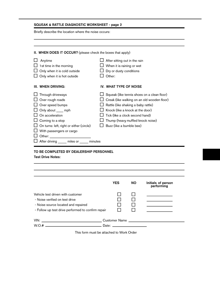
SQUEAK AND RATTLE TROUBLE DIAGNOSES

IP-15

< SYMPTOM DIAGNOSIS >

C

D

E

F

G

H

I

K

L

M

A

B

IP

N

O

P

LAIA0071E

IP-16

< REMOVAL AND INSTALLATION >

INSTRUMENT PANEL ASSEMBLY

REMOVAL AND INSTALLATION

INSTRUMENT PANEL ASSEMBLY

Exploded View

INFOID:0000000010120160

AWJIA1332ZZ

INSTRUMENT PANEL ASSEMBLY

IP-17

< REMOVAL AND INSTALLATION >

C

D

E

F

G

H

I

K

L

M

A

B

IP

N

O

P

Removal and Installation

INFOID:0000000010120161

WORK STEP

When removing instrument panel assembly, combination meter, upper meter, audio or AV control unit take

steps as per the order shown in the following chart.

1.

Sunload sensor

2.

Optical sensor (if equipped) or 
switch hole mask

3.

Switch panel

4.

Charging status indicator

5.

Instrument panel assembly

6.

Instrument mask LH

7.

Side ventilator grille LH

8.

Instrument under cover LH

9.

Instrument lower panel LH

10. Steering column upper cover

11. Steering column lower cover

12. Steering column mask

13. Instrument lower cover LH

14. USB connector

15. Heated seat switch LH

16. Instrument lower center cover

17. Heated seat switch RH

18. Auxiliary input jacks (if equipped)

19. Instrument lower cover RH

20. Glove box lid

21. Glove box cover assembly

22. Side ventilator grille RH

23. Passenger air bag module

24. Instrument mask RH

25. Audio or AV control unit

26. Upper meter

27. Cluster lid finisher

28. Meter cover

29. Combination meter

30. Cluster lid A

31. Instrument under cover RH

32. Glove box damper

33. Cluster lid C

Clip

Pawl

Metal clip

PARTS

INSTRUMENT 

PANEL

ASSEMBLY

COMBINATION

METER

UPPER
METER

AUDIO OR AV 

CONTROL UNIT

Instrument lower center cover

[1]

Instrument lower cover LH

[2]

Instrument lower cover RH

[3]

Front body side welt LH

[4]

Instrument side panel LH

[5]

Front pillar garnish LH

[6]

Instrument mask LH

[7]

Meter cover

[8]

Cluster lid finisher

[9]

[1]

[1]

Upper meter

[10]

[2]

[2]

Cluster lid A

[11]

[3]

Combination meter

[12]

[4]

Instrument under cover LH

[13]

Instrument lower panel LH

[14]

Side ventilator assembly LH

[15]

Driver air bag module

[16]

Steering wheel

[17]

Steering column covers

[18]

Combination switch

[19]

Spiral cable

[20]

Cluster lid C

[21]

[1]

Audio or AV control unit

[22]

[2]

Charging status indicator

[23]

Switch panel

[24]

Front body side welt RH

[25]

Instrument side panel RH

[26]

IP-18

< REMOVAL AND INSTALLATION >

INSTRUMENT PANEL ASSEMBLY

[ ]: Number indicates step in removal procedures. 

WARNING:

To prevent accidental explosion, before servicing, turn ignition switch OFF, disconnect 12V battery

negative terminal and wait 5 minutes or more.

CAUTION:

To prevent damage to the parts, when removing, always use a suitable tool that is made of plastic.

REMOVAL

1. Remove instrument lower center cover.

1. Apply protective tape (A) to console finisher assembly to

protect from the damage.

2. Apply protective tape (A) around the part to protect from

damage.

3. Insert suitable tool (A) between instrument lower center

cover and center console assembly to disengage the metal

clips as shown.

4. Lift up instrument lower center cover, then disconnect harness connectors.

CAUTION:

Front pillar garnish RH

[27]

Instrument mask RH

[28]

Instrument under cover RH

[29]

Glove box lid

[30]

Glove box cover assembly

[31]

Passenger air bag module harness connector

[32]

Passenger air bag module bolt

[33]

Instrument panel assembly

[34]

JMJIA6095ZZ

JMJIA6989ZZ

: Metal clip

AWJIA1333ZZ


Content   ..  878  879  880  881   ..