Nissan Leaf. Manual - part 872
FLOOR TRIM
INT-33
< REMOVAL AND INSTALLATION >
C
D
E
F
G
H
I
K
L
M
A
B
INT
N
O
P
FLOOR TRIM
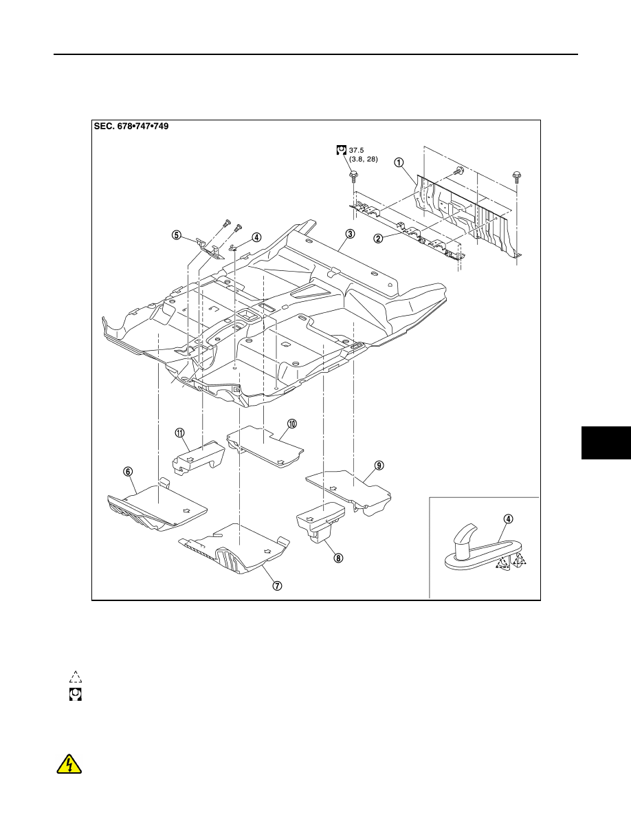
Exploded View
INFOID:0000000010119677
Removal and Installation
INFOID:0000000010119678
DANGER:
Since hybrid vehicles and electric vehicles contain a high voltage battery, there is the risk of
electric shock, electric leakage, or similar accidents if the high voltage component and vehicle are
1.
Rear seat back rear panel
2.
Luggage bar assembly
3.
Floor carpet
4.
Carpet hook
5.
Steering column hole cover
6.
Front floor spacer RH
7.
Front floor spacer LH
8.
Front floor center spacer LH
9.
Rear floor spacer LH
10. Rear floor spacer RH
11. Front floor center spacer RH
: Pawl
: N·m (kg-m, ft-lb)
JMJIA5050GB