Nissan Leaf. Manual - part 841
PRECAUTIONS
HCO-3
< PRECAUTION >
D
E
F
G
H
I
J
K
L
M
A
B
HCO
N
O
P
system uses the seat belt switches to determine the front air bag deployment, and may only deploy one front
air bag, depending on the severity of a collision and whether the front occupants are belted or unbelted.
Information necessary to service the system safely is included in the SR and SB section of this Service Man-
ual.
WARNING:
• To avoid rendering the SRS inoperative, which could increase the risk of personal injury or death in
the event of a collision which would result in air bag inflation, all maintenance must be performed by
an authorized NISSAN/INFINITI dealer.
• Improper maintenance, including incorrect removal and installation of the SRS, can lead to personal
injury caused by unintentional activation of the system. For removal of Spiral Cable and Air Bag
Module, see the SR section.
• Do not use electrical test equipment on any circuit related to the SRS unless instructed to in this
Service Manual. SRS wiring harnesses can be identified by yellow and/or orange harnesses or har-
ness connectors.
PRECAUTIONS WHEN USING POWER TOOLS (AIR OR ELECTRIC) AND HAMMERS
WARNING:
• When working near the Airbag Diagnosis Sensor Unit or other Airbag System sensors with the Igni-
tion ON or engine running, DO NOT use air or electric power tools or strike near the sensor(s) with a
hammer. Heavy vibration could activate the sensor(s) and deploy the air bag(s), possibly causing
serious injury.
• When using air or electric power tools or hammers, always switch the Ignition OFF, disconnect the
battery and wait at least three minutes before performing any service.
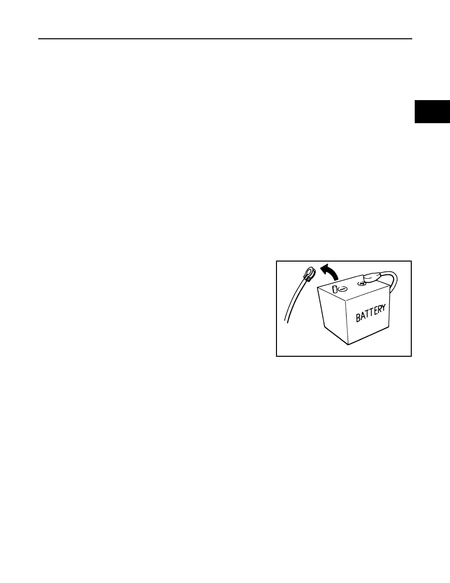
Precautions for Removing Battery Terminal
INFOID:0000000010119120
• When removing the 12V battery terminal, turn OFF the power
switch and wait at least 5 minutes.
NOTE:
ECU may be active for several minutes after the power switch is
turned OFF. If the battery terminal is removed before ECU stops,
then a DTC detection error or ECU data corruption may occur.
• Always disconnect the battery terminal within 60 minutes after
turning OFF the power switch. Even when the power switch is
OFF, the 12V battery automatic charge control may automatically
start after a lapse of 60 minutes from power switch OFF.
• Disconnect 12V battery terminal according to the following steps.
WORK PROCEDURE
1. Check that EVSE is not connected.
NOTE:
If EVSE is connected, the air conditioning system may be automatically activated by the timer A/C func-
tion.
2. Turn the power switch OFF
→ ON → OFF. Get out of the vehicle. Close all doors (including back door).
3. Check that the charge status indicator lamp does not blink and wait for 5 minutes or more.
NOTE:
If the battery is removed within 5 minutes after the power switch is turned OFF, plural DTCs may be
detected.
4. Remove 12V battery terminal within 60 minutes after turning the power switch OFF
→ ON → OFF.
CAUTION:
• After all doors (including back door) are closed, if a door (including back door) is opened before
battery terminals are disconnected, start over from Step 1.
• After turning the power switch OFF, if “Remote A/C” is activated by user operation, stop the air
conditioner and start over from Step 1.
NOTE:
Once the power switch is turned ON
→ OFF, the 12V battery automatic charge control does not start for
approximately 1 hour.
• For vehicles with the 2-batteries, be sure to connect the main battery and the sub battery before turning ON
the power switch.
NOTE:
SEF289H