Nissan Leaf. Manual - part 840


  Index      Nissan     Nissan Leaf (2011-2014 year) - Service and Repair Manual


Search            


Content   ..  838  839  840  841   ..


Nissan Leaf. Manual - part 840


DOOR MOTOR

HAC-363

< REMOVAL AND INSTALLATION >

[AUTO A/C (WITHOUT HEAT PUMP)]

C

D

E

F

G

H

J

K

L

M

A

B

HAC

N

O

P

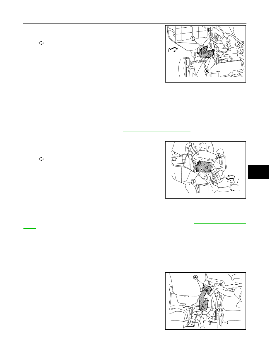
6. Remove screws (A), and then remove intake door motor (1)

from heating and cooling unit assembly.

INSTALLATION

Install in the reverse order of removal.

MODE DOOR MOTOR
MODE DOOR MOTOR : Removal and Installation

INFOID:0000000010122074

REMOVAL

1. Remove glove box cover assembly. Refer to 

IP-17, "Removal and Installation"

.

2. Disconnect mode door motor connector.
3. Remove screws (A), and then remove mode door motor (1) from

heating and cooling unit assembly.

INSTALLATION

Note the following item, and then install in the order of removal.

CAUTION:

After installing door motor, perform door motor starting position. Refer to 

HAC-277, "Work Proce-

dure"

.

AIR MIX DOOR MOTOR
AIR MIX DOOR MOTOR : Removal and Installation

INFOID:0000000010122075

REMOVAL

1. Remove instrument lower panel LH. Refer to 

IP-17, "Removal and Installation"

.

2. Remove knee protector.
3. Remove nuts (A), and then remove knee protector bracket (1).

: Vehicle front

JPIIA1832ZZ

: Vehicle front

JPIIA1833ZZ

JPIIA1891ZZ

HAC-364

< REMOVAL AND INSTALLATION >

[AUTO A/C (WITHOUT HEAT PUMP)]

DOOR MOTOR

4. Remove brake pedal assembly. Refer to 

BR-500, "Removal and Installation"

.

5. Disconnect air mix door motor connector.
6. Remove screws (A), and then remove air mix door motor (1)

from heating and cooling unit assembly.

INSTALLATION

Note the following item, and then install in the order of removal.

CAUTION:

After installing door motor, perform door motor starting position. Refer to 

HAC-277, "Work Proce-

dure"

.

: Vehicle front

JPIIA1834ZZ

HCO-1

ELECTRIC POWER TRAIN

D

E

F

G

H

I

J

K

L

M

SECTION 

HCO

A

B

HCO

N

O

P

CONTENTS

HIGH VOLTAGE COOLING SYSTEM

PRECAUTION ...............................................

2

PRECAUTIONS ...................................................

2

Precaution for Technicians Using Medical Electric 

......

2

Point to Be Checked Before Starting Maintenance 
Work ........................................................................
..

2

Precaution for Supplemental Restraint System 
(SRS) "AIR BAG" and "SEAT BELT PRE-TEN-
SIONER" .................................................................
..

2

Precautions for Removing Battery Terminal  .............

3

PREPARATION ............................................

5

PREPARATION ...................................................

5

Commercial Service Tools .......................................

5

SYSTEM DESCRIPTION  ..............................

6

COMPONENT PARTS  ........................................

6

Radiator .....................................................................

6

Cooling fan (electric fan)  ...........................................

6

Electric water pump ...................................................

6

SYSTEM ..............................................................

7

High Voltage Cooling System  ...................................

7

BASIC INSPECTION  ....................................

9

RADIATOR ..........................................................

9

Inspection ..................................................................

9

SYMPTOM DIAGNOSIS  ..............................

10

OVERHEATING CAUSE ANALYSIS .................

10

Troubleshooting Chart .............................................

10

PERIODIC MAINTENANCE  ........................

11

COOLANT .........................................................

11

Inspection ................................................................

11

Draining ...................................................................

11

Refilling ....................................................................

12

RESERVOIR TANK CAP  ..................................

13

Inspection ................................................................

13

REMOVAL AND INSTALLATION ...............

14

RADIATOR ........................................................

14

Exploded View .........................................................

14

Removal and Installation  .........................................

15

Inspection ................................................................

21

COOLING FAN ..................................................

22

Exploded View .........................................................

22

Removal and Installation  .........................................

22

Disassembly and Assembly .....................................

23

ELECTRIC WATER PUMP  ...............................

25

Exploded View .........................................................

25

Removal and Installation  .........................................

25

SERVICE DATA AND SPECIFICATIONS 
(SDS) ............................................................

27

SERVICE DATA AND SPECIFICATIONS 
(SDS) .................................................................

27

Periodical Maintenance Specification ......................

27

HCO-2

< PRECAUTION >

PRECAUTIONS

PRECAUTION

PRECAUTIONS

Precaution for Technicians Using Medical Electric

INFOID:0000000010119117

OPERATION PROHIBITION

WARNING:

• Parts with strong magnet is used in this vehicle. 

• Technicians using a medical electric device such as pacemaker must never perform operation on the

vehicle, as magnetic field can affect the device function by approaching to such parts.

NORMAL CHARGE PRECAUTION

WARNING:

• If a technician uses a medical electric device such as an implantable cardiac pacemaker or an

implantable cardioverter defibrillator, the possible effects on the devices must be checked with the

device manufacturer before starting the charge operation.

• As radiated electromagnetic wave generated by PDM (Power Delivery Module) at normal charge

operation may affect medical electric devices, a technician using a medical electric device such as

implantable cardiac pacemaker or an implantable cardioverter defibrillator must not approach motor

room [PDM (Power Delivery Module)] at the hood-opened condition during normal charge operation.

PRECAUTION AT TELEMATICS SYSTEM OPERATION

WARNING:

• If a technician uses implantable cardiac pacemaker or implantable cardioverter defibrillator (ICD),

avoid the device implanted part from approaching within approximately 220 mm (8.66 in) from inte-

rior/exterior antenna.

• The electromagnetic wave of TCU might affect the function of the implantable cardiac pacemaker or

the implantable cardioverter defibrillator (ICD), when using the service, etc.

• If a technician uses other medical electric devices than implantable cardiac pacemaker or implant-

able cardioverter defibrillator (ICD), the electromagnetic wave of TCU might affect the function of the

device. The possible effects on the devices must be checked with the device manufacturer before

TCU use.

PRECAUTION AT INTELLIGENT KEY SYSTEM OPERATION

WARNING:

• If a technician uses implantable cardiac pacemaker or implantable cardioverter defibrillator (ICD),

avoid the device implanted part from approaching within approximately 220 mm (8.66 in) from inte-

rior/exterior antenna.

• The electromagnetic wave of Intelligent Key might affect the function of the implantable cardiac

pacemaker or the implantable cardioverter defibrillator (ICD), at door operation, at each request

switch operation, or at engine starting.

• If a technician uses other medical electric devices than implantable cardiac pacemaker or implant-

able cardioverter defibrillator (ICD), the electromagnetic wave of Intelligent Key might affect the

function of the device. The possible effects on the devices must be checked with the device manu-

facturer before Intelligent Key use.

Point to Be Checked Before Starting Maintenance Work

INFOID:0000000010119118

The high voltage system may starts automatically. It is required to check that the timer air conditioner

and timer charge (during EVSE connection) are not set before starting maintenance work.

NOTE:

If the timer air conditioner or timer charge (during EVSE connection) is set, the high voltage system starts

automatically even when the power switch is in OFF state.

Precaution for Supplemental Restraint System (SRS) "AIR BAG" and "SEAT BELT 
PRE-TENSIONER"

INFOID:0000000010417773

The Supplemental Restraint System such as “AIR BAG” and “SEAT BELT PRE-TENSIONER”, used along

with a front seat belt, helps to reduce the risk or severity of injury to the driver and front passenger for certain

types of collision. This system includes seat belt switch inputs and dual stage front air bag modules. The SRS


Content   ..  838  839  840  841   ..