Nissan Leaf. Manual - part 808
SYSTEM
HAC-235
< SYSTEM DESCRIPTION >
[AUTO A/C (WITHOUT HEAT PUMP)]
C
D
E
F
G
H
J
K
L
M
A
B
HAC
N
O
P
AIR DISTRIBUTION
AUTOMATIC AIR CONDITIONING SYSTEM : PTC Heater Control
INFOID:0000000010121949
DESCRIPTION
• Based on the air mix door position and signals input from each sensor, the A/C auto amp. calculates the
PTC heater outlet air temperature.
• A/C auto amp. calculates the PTC heater operating rate so that the calculated PTC heater outlet air temper-
ature is achieved, and transmits the PTC heater operating rate request signal to the PTC heater via LIN
communication.
• Based on the A/C auto amplifier command, the control circuit inside the PTC heater controls the PTC heater
output by the PWM method.
NOTE:
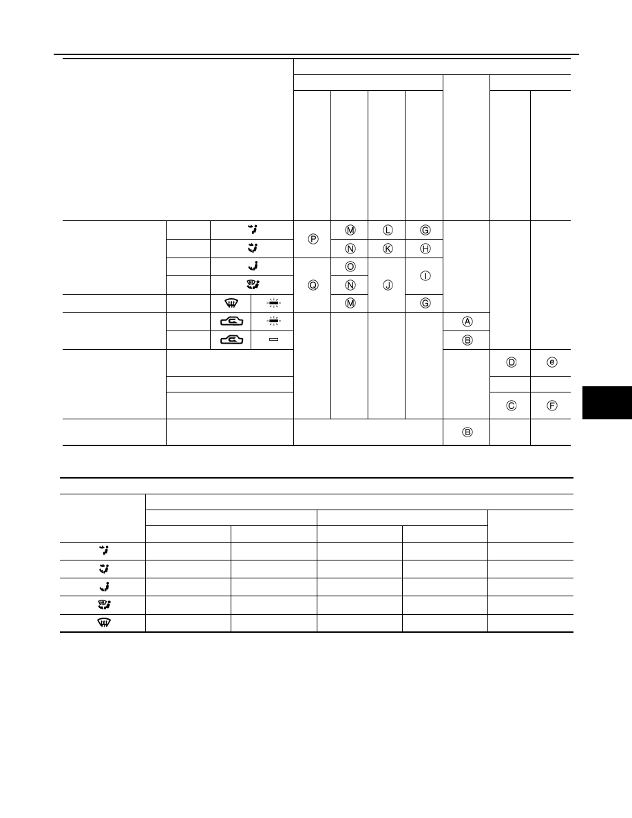
MODE switch
*
VENT
—
—
—
B/L
FOOT
D/F
DEF switch
ON
Intake switch
*
REC
—
—
—
—
FRE
Temperature control
switch
Full cold
16.0
°C
—
16.5
°C – 29.5°C
AUTO
AUTO
Full hot
30.0
°C
ON/OFF switch
OFF
Fixed at the position where the ON/
OFF switch is pressed
—
—
Switch position
Door position
Mode door
In
ta
ke
do
or
Air mix door
Cen
ter ve
nt
ila
to
r/
de
fr
os
te
r do
or
Sub
- de
fr
ost
er do
or
Si
de
v
en
til
at
or
do
or
Fo
ot doo
r
Up
pe
r a
ir m
ix
do
or
Lowe
r a
ir m
ix
do
or
Discharge air flow
MODE/DEF setting
potion
Air outlet/distribution (Approx.)
Ventilator
Foot
Defroster
Center
Side
Front
Rear
50%
50%
—
—
—
30%
30%
28%
12%
—
—
15%
45%
20%
20%
—
15%
32%
13%
40%
—
15%
—
—
85%