Nissan Leaf. Manual - part 807


  Index      Nissan     Nissan Leaf (2011-2014 year) - Service and Repair Manual


Search            


Content   ..  805  806  807  808   ..


Nissan Leaf. Manual - part 807


SYSTEM

HAC-231

< SYSTEM DESCRIPTION >

[AUTO A/C (WITHOUT HEAT PUMP)]

C

D

E

F

G

H

J

K

L

M

A

B

HAC

N

O

P

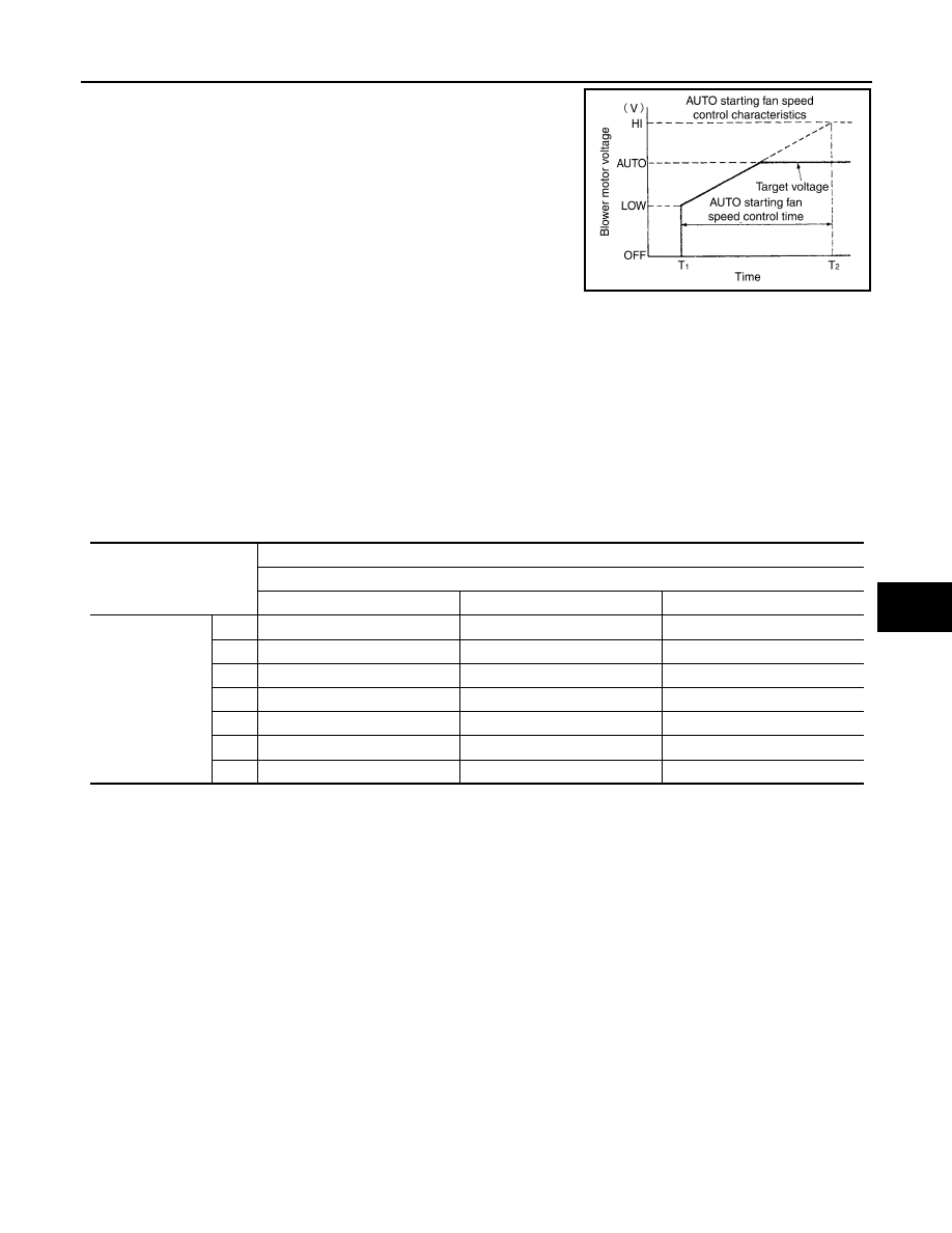
When the blower fan motor is activated by the AUTO control, voltage

to blower fan motor increases gradually and then the amount of air

flow increases gradually. (Approximately 138 seconds for air flow to

reach HI from LOW)

STARTING AIR FLOW CONTROL AT HIGH INTERIOR AIR TEMPERATURE

When evaporator temperature is high [intake air temperature sensor value is 35

°C (95°F) or more], to prevent

a hot discharged air flow, A/C auto amp. suspends blower motor activation for approximately three seconds so

that evaporator is cooled by refrigerant.

AIR FLOW CONTROL AT MODE DOOR MOTOR OPERATION

If the mode motor starts when the air flow corresponds to a voltage of 8.6 V or more applied to the blower fan

motor, the A/C auto amp. performs control that fixes the voltage applied to the blower fan motor at 8.5 V, tem-

porarily decreasing the air flow and ensuring that the mode door operates smoothly.

MANUAL AIR FLOW CONTROL

When the fan switch is operated, automatic control is cancelled and the desired fan speed (1 – 7) can be

selected.

AUTOMATIC AIR CONDITIONING SYSTEM : Air Inlet Control

INFOID:0000000010121945

• Manual control by the REC switch and FRE switch is given priority for inlet selection.

• When the DEF switch is pressed, the inlet is fixed at fresh air intake.

• During automatic inlet control, when the electric compressor is ON and the ambient temperature is high, the

intake is fixed at recirculation.

• When the A/C system is OFF, the inlet is fixed at fresh air intake.

• During automatic inlet control when the ambient temperature is except above, the A/C auto amp. changes

the intake control status according to the ambient temperature and the operating status of the electric com-

pressor, discharge air flow, and outlet operating status.

JSIIA1775GB

Voltage applied to blower fan motor (V)

Mode switch

VENT, B/L

FOOT, D/F

DEF

Fan speed
(When manual 
control is selected)

1st

4.0

4.0

4.0

2nd

5.4

5.2

5.3

3rd

6.8

6.3

6.7

4th

8.3

7.5

8.0

5th

9.7

8.7

9.3

6th

11.1

9.8

10.7

7th

12.5

11.0

12.5

HAC-232

< SYSTEM DESCRIPTION >

[AUTO A/C (WITHOUT HEAT PUMP)]

SYSTEM

AUTOMATIC AIR CONDITIONING SYSTEM : Electric Power Distribution Control

INFOID:0000000010121946

DESCRIPTION

• Based on the vehicle status, battery remaining energy, and other factors, VCM calculates the electrical

power needed to operate the A/C system, and sends this value to the A/C auto amp. via EV CAN communi-

cation.

• Based on the ambient sensor signal, inlet position, outlet position, target air mix door position, and other

information, the A/C auto amp. calculates the electrical power used by the electric compressor and PTC ele-

ment heater. If the total exceeds the electric power consumption permitted by the VCM, then the operating

rate of the electric compressor and PTC element heater are reduced to lower the power consumption.

WARM-UP AND COOL-DOWN CONTROL

For the first 10 minutes after the power switch is turned ON, heating/cooling operation at maximum capacity is

possible based on a judgment by the A/C auto amp. (however this does not occur in ECO mode).

AUTOMATIC AIR CONDITIONING SYSTEM : Compressor Control

INFOID:0000000010121947

DESCRIPTION

• If the conditions for electric compressor operation are met while the blower fan motor is operating, then

based on the various input signals, the A/C auto amp. calculates the compressor target speed that produces

the target temperature (4–12

°C) for the evaporator outlet temperature, and sends a speed command to the

electric compressor via a communications signal.

Compressor

Mode switch

Ambient temperature (temperature detected by ambient sensor)

14

°C or less

15

°C or more

ON

VENT

B/L

30% recirculation

Control according to the target air mix door position

FOOT

D/F

Fresh air intake

OFF

VENT

B/L

30% recirculation

Fresh air intake

FOOT

D/F

Fresh air intake

JMIIA0711GB

SYSTEM

HAC-233

< SYSTEM DESCRIPTION >

[AUTO A/C (WITHOUT HEAT PUMP)]

C

D

E

F

G

H

J

K

L

M

A

B

HAC

N

O

P

• The electric compressor receives the A/C auto amp. command and controls the motor speed by means of its

built-in inverter circuit, then transmits this status by communications.

Evaporator Protection Control

• When intake air temperature sensor detects that air temperature

after passing through evaporator is 1

°C or less, A/C auto amp.

sends a request to the electric compressor for a speed of 0 rpm,

stopping compressor operation.

• When the air temperature after passing through evaporator

reaches 4

°C or more, operation of the electric compressor is

resumed.

Compressor Protection Control at Pressure Malfunction

• When the refrigerant pressure on the high-pressure side (detected by the refrigerant pressure sensor) that is

received from the VCM via EV system CAN communication is as shown below, the A/C auto amp. stops the

compressor.

- Approximately 2.65 MPa (Approximately 27.0 kg/cm

2

) or more

- Approximately 0.14 MPa (Approximately 1.4 kg/cm

2

) or less

• When the refrigerant pressure on the high-pressure side returns to the range below, the A/C auto amp.

resumes operation of the electric compressor. 

- Approximately 1.55 MPa (Approximately 15.8 kg/cm

2

) or less

- Approximately 0.16 MPa (Approximately 1.6 kg/cm

2

) or more

AUTOMATIC AIR CONDITIONING SYSTEM : Door Control

INFOID:0000000010121948

SWITCH AND THEIR CONTROL FUNCTION

JSIIA1649GB

JSIIA1650GB

HAC-234

< SYSTEM DESCRIPTION >

[AUTO A/C (WITHOUT HEAT PUMP)]

SYSTEM

Intake door

Blower motor

Air conditioner filter

Evaporator

Upper air mix door

Lower air mix door

PTC heater core

Foot door

Side ventilator door

Sub-defroster door

Center ventilator/defroster door

Fresh air

Recirculation air

Discharge air

Defroster

Center ventilator

Side ventilator

Foot

Rear foot

Switch position

Door position

Mode door

In

ta

ke

 do

or

Air mix door

Ce

nt

er v

en

tilat

or/d

efro

st

er d

oo

r

Su

b- de

fros

te

do

or

Si

de

 v

ent

ila

to

r do

or

Fo

ot

 do

or

Up

pe

r ai

r mi

x do

or

Lo

we

r ai

r mi

x do

or

AUTO switch

ON

AUTO

ALIIA0791ZZ


Content   ..  805  806  807  808   ..