Nissan Leaf. Manual - part 795
AUTOMATIC AIR CONDITIONING SYSTEM
HAC-183
< SYMPTOM DIAGNOSIS >
[AUTO A/C (WITH HEAT PUMP)]
C
D
E
F
G
H
J
K
L
M
A
B
HAC
N
O
P
SYMPTOM DIAGNOSIS
AUTOMATIC AIR CONDITIONING SYSTEM
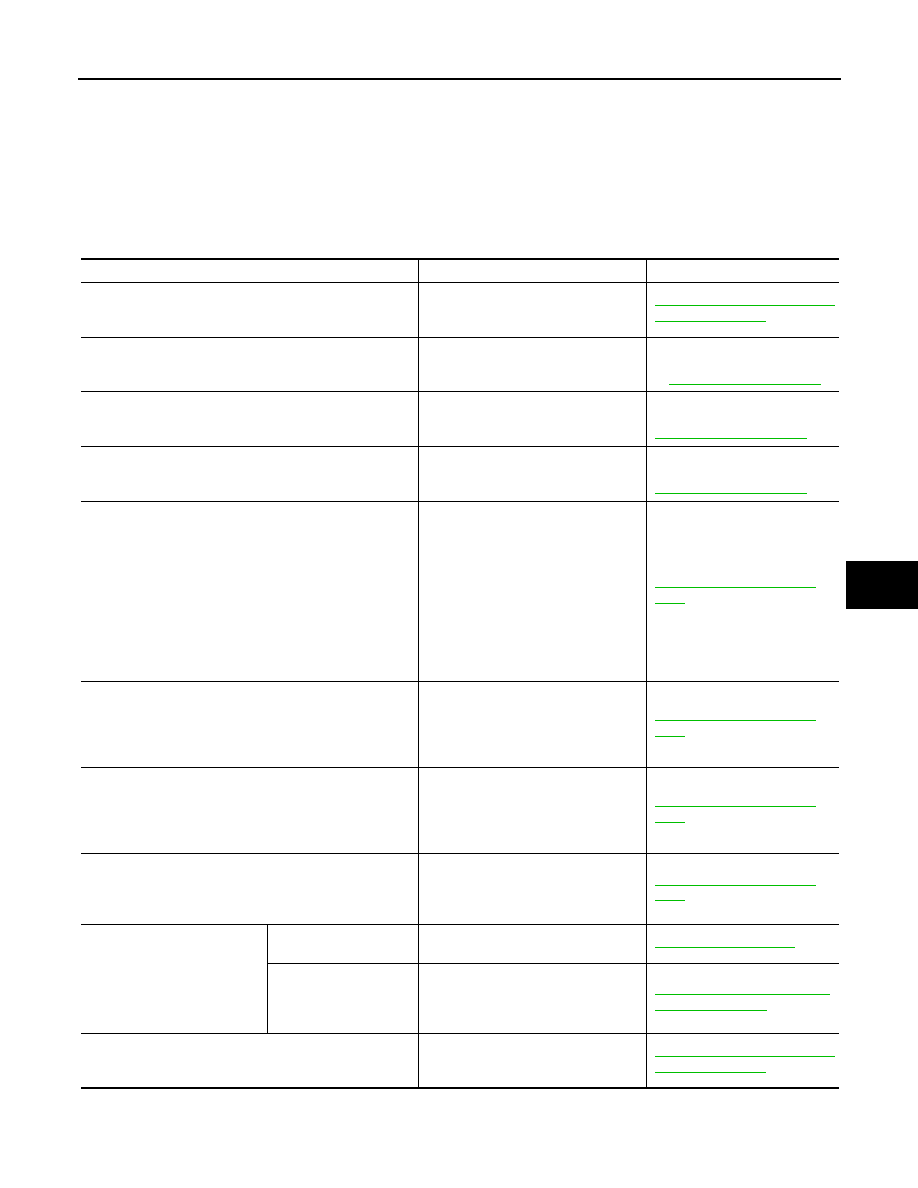
Symptom Table
INFOID:0000000010121885
NOTE:
Perform self-diagnoses with CONSULT before performing the symptom diagnosis. If any DTC is detected,
perform the corresponding diagnosis.
Symptom
Corresponding malfunctioning part
Check item/Reference
• Air conditioning system does not activate.
• Air conditioning system cannot be controlled.
• A/C auto amp. ignition power supply
and ground circuit
• A/C auto amp.
HAC-173, "A/C AUTO AMP. : Di-
agnosis Procedure"
Discharge air temperature does not change.
Air mix door motor system installation
condition
Check air mix door motor sys-
tem is properly installed. Refer
to
.
Air outlet does not change.
Mode door motor system installation
condition
Check mode door motor system
is properly installed. Refer to
.
Air inlet does not change.
Intake door motor system installation
condition
Check intake door motor system
is properly installed. Refer to
.
Blower motor does not operates or operation speed is not
normal.
• Blower motor power supply circuit
• Blower motor control circuit
• A/C auto amp. ignition power supply
circuit
• Power transistor power supply and
ground circuit
• Power transistor control signal cir-
cuit
• Blower motor
• Power transistor
• A/C auto amp.
HAC-175, "Diagnosis Proce-
dure"
Compressor does not operate.
• The circuit between VCM and refrig-
erant pressure sensor
• Refrigerant pressure sensor
• Blower fan ON signal circuit
• A/C auto amp.
HAC-186, "Diagnosis Proce-
dure"
• Insufficient cooling.
• No cool air comes out. (Air flow volume is normal.)
• Cooler cycle
• Air leakage from each duct
• A/C auto amp. connection recogni-
tion signal circuit
• Temperature setting trimmer
HAC-184, "Diagnosis Proce-
dure"
• Insufficient heating.
• No warm air comes out. (Air flow volume is normal.)
• Cooler cycle
• Air leakage from each duct
• Temperature setting trimmer
• A/C auto amp. connection
HAC-185, "Diagnosis Proce-
dure"
Noise is heard when the A/C
system operates.
During compressor op-
eration.
Cooler cycle
During blower motor op-
eration.
• Mixing any foreign object in blower
motor
• Blower motor fan breakage
• Blower motor rotation inferiority
HAC-177, "Component Inspec-
tion (Blower Motor)"
• Memory function does not operate normally.
• The setting is not maintained. (It returns to initial condi-
tion.)
• A/C auto amp. battery power supply
circuit
• A/C auto amp.