Nissan Leaf. Manual - part 734


  Index      Nissan     Nissan Leaf (2011-2014 year) - Service and Repair Manual


Search            


Content   ..  732  733  734  735   ..


Nissan Leaf. Manual - part 734


HA-58

< REMOVAL AND INSTALLATION >

[WITH HEAT PUMP SYSTEM]

HEATING AND COOLING UNIT ASSEMBLY

DANGER:


Touching high voltage components without using the appropriate protective equipment will

cause electrocution.

CAUTION:

For voltage measurements, use a tester which can measure to 500 V or higher.

2. Use the refrigerant recovery equipment (for HFC134a) and recover the refrigerant. Refer to 

HA-27, "Recy-

cle Refrigerant"

.

3. Remove cowl top extension. Refer to 

EXT-19, "Removal and Installation"

.

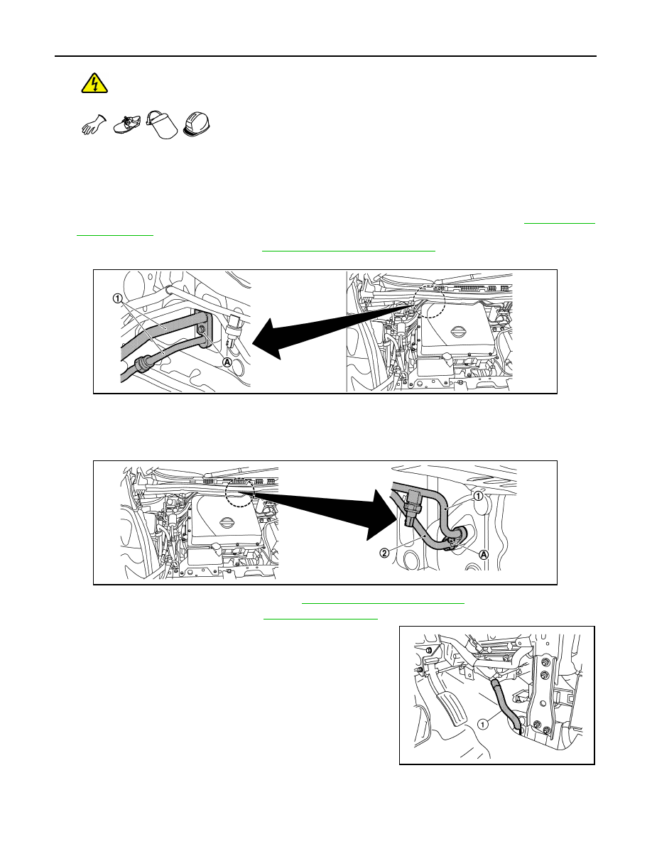
4. Remove bolt (A), and then disconnect low-pressure pipe (1) and high-pressure pipe (2) from evaporator.

CAUTION:

To prevent the inclusion of foreign matter, use a cap or vinyl tape to seal off the connection ports

of the pipes and evaporator from the atmosphere.

5. Remove bolt (A) then disconnect high pressure pipes (1) and (2) from inner condenser.

6. Remove instrument panel assembly. Refer to 

IP-17, "Removal and Installation"

.

7. Remove side ventilator duct. Refer to 

IP-16, "Exploded View"

.

8. Disconnect drain hose (1).

Standard

: 5 V or less 

JMIIA2659ZZ

JMIIA2658ZZ

AWIIA1734ZZ

HEATING AND COOLING UNIT ASSEMBLY

HA-59

< REMOVAL AND INSTALLATION >

[WITH HEAT PUMP SYSTEM]

C

D

E

F

G

H

J

K

L

M

A

B

HA

N

O

P

9. Remove nuts (A), and then remove instrument stay (1).

10. Remove screws (A), and then remove fuse block (J/B) (1).

11. Remove bolts (A) of ground wires from steering member.

12. Remove all harness connectors and mounting nuts necessary to allow steering column assembly to be

moved. Refer to 

ST-35, "Removal and Installation"

.

13. Move steering column assembly to secure work space.
14. Remove all harness connectors and clips necessary to allow steering member to be removed. Move main

harness aside and secure work space so that steering member can be easily removed.

AWIIA1665ZZ

JPIIA1789ZZ

JPIIA1790ZZ

HA-60

< REMOVAL AND INSTALLATION >

[WITH HEAT PUMP SYSTEM]

HEATING AND COOLING UNIT ASSEMBLY

15. Remove bolts (A) and (B), and then remove steering member (1) from the vehicle.

CAUTION:

When removing steering member, 2 workers are required to prevent it from dropping.

16. Remove heating and cooling unit assembly from the vehicle.

INSTALLATION

Note the following items, and then install in the reverse order of removal.

CAUTION:

• To prevent degradation in insulation performance, use special electric compressor oil as the com-

pressor oil.

• In order to prevent conventional PAG oil from becoming mixed in, never reuse recovered compres-

sor oil and instead always use new oil. The use of oil including the conventional PAG oil may

degrade the performance of insulation.

• To prevent performance degradation, never use a fluorescent agent in order to detect refrigerant

leakage. Also be careful that a fluorescent agent never enter the oil.

• To prevent leakage of refrigerant, replace the O-ring with a new one. Apply a coat of compressor oil

to the O-ring prior to installation.

• Perform a check for refrigerant leakage when charging with refrigerant. Refer to 

HA-26, "Check

Refrigerant Leakage"

.

EVAPORATOR
EVAPORATOR : Removal and Installation

INFOID:0000000010122129

REMOVAL

1. Remove heating and cooling unit assembly. Refer to 

HA-57, "HEATING AND COOLING UNIT ASSEM-

BLY : Removal and Installation"

2. Disassemble the heating and cooling unit assembly, and then remove evaporator assembly.
3. Remove intake sensor from evaporator assembly.

INSTALLATION

Note the following items, and then install in the reverse order of removal.

CAUTION:

• To prevent leakage of refrigerant, replace the O-ring with a new one. Apply a coat of compressor oil

to the O-ring prior to installation.

JPIIA1791ZZ

HEATING AND COOLING UNIT ASSEMBLY

HA-61

< REMOVAL AND INSTALLATION >

[WITH HEAT PUMP SYSTEM]

C

D

E

F

G

H

J

K

L

M

A

B

HA

N

O

P

• When installing the new evaporator, be sure to install the intake sensor in the same position as

before it was removed.

• When removing or installing the intake sensor, be sure not to rotate the bracket insertion part. Fail-

ure to do this may cause damage to the evaporator.

• After installing a new evaporator, adjust the compressor oil level. Refer to 

HA-29, "Lubricant Adjust-

ing Procedure for Components Replacement Except Compressor"

.

INNER CONDENSER
INNER CONDENSER : Removal and Installation

INFOID:0000000010122130

REMOVAL

1. Remove heating and cooling unit assembly. Refer to 

HA-57, "HEATING AND COOLING UNIT ASSEM-

BLY : Removal and Installation"

.

2. Remove screws (A) and (B), then remove PTC heater shield LH.

3. Remove screws (A), then remove inner condenser pipe cover.

4. Remove inner condenser cover screws (A), then remove inner

condenser from heating and cooling unit assembly.

INSTALLATION

Install in the reverse order of removal.

JMIIA2682ZZ

JMIIA2683ZZ

JMIIA2684ZZ


Content   ..  732  733  734  735   ..