Nissan Leaf. Manual - part 726


  Index      Nissan     Nissan Leaf (2011-2014 year) - Service and Repair Manual


Search            


Content   ..  724  725  726  727   ..


Nissan Leaf. Manual - part 726


HA-26

< BASIC INSPECTION >

[WITH HEAT PUMP SYSTEM]

REFRIGERANT

REFRIGERANT

Description

INFOID:0000000010122103

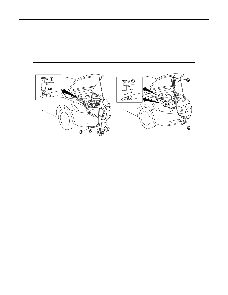
CONNECTION OF SERVICE TOOLS AND EQUIPMENT

CAUTION:

To prevent fluorescent indicator from entering, prepare and use exclusive hose for EV (electric vehi-

cle) and HEV (hybrid vehicle) when connecting recovery/recycling/recharging equipment.

Check Refrigerant Leakage

INFOID:0000000010122104

DETECTING LEAKAGES WITH FLUORESCENT INDICATOR

CAUTION:

Do not use fluorescent indicators as these may reduce the insulation resistance.

CHECK REFRIGERANT LEAKAGE USING ELECTRICAL LEAK DETECTOR

CAUTION:

Be careful of the following items so that inaccurate checks or misidentifications are avoided.

• Do not allow refrigerant vapor, shop chemical vapors, cigarette smoke, or others around the vehicle.

• Always check refrigerant leakage in a low air flow environment so that refrigerant may not disperse

when leakage occurs.

1. Connect recovery/recycling/recharging equipment (for HFC-134a) or manifold gauge set to A/C service

valve.

2. Check that refrigerant gas pressure is 345 kPa (3.5 kg/cm

2

, 50 psi) or more when temperature is 16

°C

(61

°F) or more. When pressure is lower than the specified value, fully recover all refrigerant and then

charge with refrigerant from the service can to the specified level.

NOTE:
Leakages may not be detected if refrigerant gas pressure is 345 kPa (3.5 kg/cm

2

, 50 psi) less when tem-

perature is 16

°C (61°F) or less.

3. Clean area where refrigerant leakage check is performed, and check refrigerant leakage along all sur-

faces of pipe connections and A/C system components using electrical leak detector probe.

CAUTION:

• Even when a leakage point has been found, always continue and complete checking along all

pipe connections and A/C system components for additional leakage.

• When a leakage is detected, clean leakage area using compressed air and check again.

1.

Shut-off valve

2.

A/C service valve

3.

Recovery/recycling/recharging 
equipment (for HFC-134a)

4.

Vacuum pump

5.

Manifold gauge set

JPIIA0127ZZ

REFRIGERANT

HA-27

< BASIC INSPECTION >

[WITH HEAT PUMP SYSTEM]

C

D

E

F

G

H

J

K

L

M

A

B

HA

N

O

P

• When checking leakage of cooling unit inside, always clean inside of drain hose so that the

probe surface may not be exposed to water or dirt.

NOTE:

• Always check leakage starting from high-pressure side and continue to low-pressure side.

• When checking for leakage inside cooling unit, operate blower motor for 15 minutes or more at the max-

imum fan speed, and then insert electrical leak detector probe into drain hose and leave it inserted for

10 minutes or more.

• When disconnecting shut-off valve that is connected to A/C service valve, always evacuate remaining

refrigerant so that misidentification can be avoided.

4. Repair or replace parts where refrigerant leakage is detected. (Leakage is detected but leakage location is

unknown. GO TO 5.)

5. Start the vehicle and set A/C control in the following conditions.

• A/C switch: ON

• Mode switch: Ventilation set

• Intake switch: Recirculation set

• Temperature setting: Full cold

• Blower motor speed: Maximum speed set 

6. Operate A/C for 2 minutes or longer.
7. Stop the A/C. Check again for refrigerant leakage. GO TO 3.

NOTE:

• Start refrigerant leakage check immediately after the A/C is

stopped.

• When refrigerant circulation is stopped, pressure on the low-

pressure side rises gradually, and after this, pressure on the

high-pressure side falls gradually.

• The higher the pressure is, the easier it is to find the refriger-

ant leakage.

Recycle Refrigerant

INFOID:0000000010122105

WARNING:

• Always use HFC-134a for refrigerant gas. If CFC-12 is accidentally charged, compressor is damaged

due to insufficient lubrication.

• Always observe and follow precautions described on refrigerant container. Incorrect handling may

result in an explosion of refrigerant container, frostbite, or the loss of eyesight.

• Do not breathe refrigerant gas and lubricant vapor or mist. Exposure my irritate eyes, nose, or

throat.

• Do not allow HFC-134a to be exposed to an open flame or others because it generates poisonous

gas when in contact with high temperature objects. Keep workshop well ventilated.

• To prevent fluorescent indicator from entering, prepare and use exclusive hose for EV (electric vehi-

cle) and HEV (hybrid vehicle) when connecting recovery/recycling/recharging equipment.

1. Perform oil return operation. Refer to 

HA-29, "Perform Lubricant Return Operation"

. (If refrigerant or lubri-

cant leakage is detected in a large amount, omit this step, and then GO TO 2.)

CAUTION:

Do not perform lubricant return operation if a large amount of refrigerant or lubricant leakage is

detected.

2. Check gauge pressure readings of recovery/recycling/recharging equipment (for HFC-134a). When

remaining pressure exists, recycle refrigerant from high-pressure hose and low-pressure hose.

NOTE:

Follow manufacturer instructions for the handling or maintenance of the equipment. Never fill the equip-

ment with non-specified refrigerant.

3. Remove A/C service valve cap from the vehicle.
4. Connect recovery/recycling/recharging equipment (for HFC-134a) to the A/C service valve.
5. Operate recovery/recycling/recharging equipment (for HFC-134a), and recycle refrigerant from the vehi-

cle.

SHA839E

HA-28

< BASIC INSPECTION >

[WITH HEAT PUMP SYSTEM]

REFRIGERANT

6. Evacuate air for 10 minutes or more to remove any remaining refrigerant integrated to compressor lubri-

cant, etc.

7. Refrigerant recycle operation is complete.

Charge Refrigerant

INFOID:0000000010122106

WARNING:

• Always use HFC-134a for refrigerant. If CFC-12 is accidentally charged, compressor is damaged due

to insufficient lubrication.

• Always observe and follow precautions described on refrigerant container. Incorrect handling may

result in an explosion of refrigerant container, frostbite, or the loss of eyesight.

• When charging with refrigerant gas, charge with the prescribed amount from a new service can.

• Do not breathe refrigerant gas and lubricant vapor or mist. Exposure my irritate eyes, nose, or

throat.

• Do not allow HFC-134a to be exposed to an open flame or others because it generates poisonous

gas when in contact with high temperature objects. Keep workshop well ventilated.

• To prevent fluorescent indicator from entering, prepare and use exclusive hose for EV (electric vehi-

cle) and HEV (hybrid vehicle) when connecting recovery/recycling/recharging equipment.

1. Connect manifold gauge (for HFC-134a) to the service valve.
2. Connect vacuum pump to manifold gauge and operate the pump. Apply vacuum to the cooler cycle for

approximately 25 minutes or longer.

CAUTION:

Evacuate air for 15 minutes or more if the parts are replaced.

3. Check the airtightness of A/C system for 25 minutes or more. If pressure raises more than the specified

level, charge A/C system with approximately 200 g (0.4 lb) refrigerant and check that there is no refriger-

ant leakage. Refer to 

HA-26, "Check Refrigerant Leakage"

.

CAUTION:

Check the airtightness for 15 minutes or more if the parts are replaced.

4. If parts other than compressor were replaced, add compressor oil according to parts that were replaced.

Refer to 

HA-29, "Lubricant Adjusting Procedure for Components Replacement Except Compressor"

.

5. Charge the A/C system from a service can with the specified amount of refrigerant.
6. Check that A/C system operates normally.
7. Disconnect manifold gauge.
8. Install A/C service valve cap.
9. Refrigerant charge is complete.

LUBRICANT

HA-29

< BASIC INSPECTION >

[WITH HEAT PUMP SYSTEM]

C

D

E

F

G

H

J

K

L

M

A

B

HA

N

O

P

LUBRICANT

Description

INFOID:0000000010122107

MAINTENANCE OF LUBRICANT LEVEL

The compressor lubricant is circulating in the system together with the refrigerant. It is necessary to fill com-

pressor with lubricant when replacing A/C system parts or when a large amount of refrigerant leakage is

detected. It is important to always maintain lubricant level within the specified level. Or otherwise, the following

conditions may occur.

• Insufficient lubricant amount: Stuck compressor

• Excessive lubricant amount: Insufficient cooling (caused by insufficient heat exchange)

Inspection

INFOID:0000000010122108

If there is a malfunction (abnormal noise from inside, cooling failure) in the compressor unit, check the com-

pressor oil.

1.

CHECK COMPRESSOR OIL

1. Remove electric compressor. 

HA-37, "Exploded View"

.

2. Refer to the diagram and judge the drained compressor oil.

Judgment result 1:>>Replace only compressor.

Judgment result 2:>>Replace compressor and liquid tank.

Perform Lubricant Return Operation

INFOID:0000000010122109

CAUTION:

If a large amount of refrigerant or lubricant leakage is detected, never perform lubricant return opera-

tion.
1. Start the vehicle and set to the following conditions.

• A/C switch: ON

• Blower motor speed: Maximum speed set 

• Intake switch: Recirculation set

• Temperature setting: Full cold

2. Perform lubricant return operation for approximately 10 minutes.
3. Stop A/C operation.
4. Oil return operation is complete.

Lubricant Adjusting Procedure for Components Replacement Except Compressor

INFOID:0000000010122110

Fill with lubricant for the amount that is calculated according to the following conditions.
Example: Lubricant amount to be added when replacing evaporator [m  (Imp fl oz)] = 35 (1.2) + 

α

Specified lubricant

ND-OIL 11 (special oil for electric compressors)

JSIIA0927GB


Content   ..  724  725  726  727   ..