Nissan Leaf. Manual - part 724


  Index      Nissan     Nissan Leaf (2011-2014 year) - Service and Repair Manual


Search            


Content   ..  722  723  724  725   ..


Nissan Leaf. Manual - part 724


HA-18

< SYSTEM DESCRIPTION >

[WITH HEAT PUMP SYSTEM]

COMPONENT PARTS

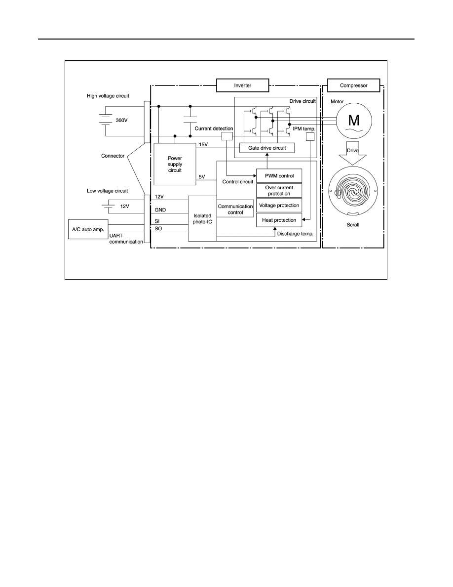
• The inverter communicates with A/C auto amp., and uses PWM control

Note

 to control the motor speed via

the drive circuit.

NOTE:

• PWM (Pulse Width Modulation) is a system that controls current and voltage by changing the duty ratio of

a constant frequency pulse wave.

• PWM is used as the adjustment method of output voltage when inverter is used as a power supply for con-

trolling motor speed.

• PWM changes voltage application time (pulse width) using a semiconductor element and controls motor

speed.

• The IPM contains an internal protection circuit, and uses the inverter control circuit to monitor for an

increase in motor drive circuit temperature in order to prevent circuit overheating.

• The motor uses a DC brushless motor, with speed control performed by the inverter drive circuit.

JMIIA2059GB

COMPONENT PARTS

HA-19

< SYSTEM DESCRIPTION >

[WITH HEAT PUMP SYSTEM]

C

D

E

F

G

H

J

K

L

M

A

B

HA

N

O

P

• A scroll-type compressor is used. The motor drive force is used to rotate the moveable scroll and perform

refrigerant intake, compression, and discharge.

Orifice

INFOID:0000000010122094

• An orifice is used to control the pressure and temperature of the

refrigerant.

• Both the heating and cooling systems use an orifice tube.

PTC

• PTC stands for "Positive Temperature Coefficient", and is a ceramic material with barium titanate as the pri-

mary component.

• When current is applied, it heats up. Upon reaching a certain tem-

perature (Curie temperature) the resistance suddenly increases,

limiting the current, and maintaining a constant amount of heating.

Accumulator

INFOID:0000000010122095

• An accumulator is used to store and clean the refrigerant.

JSIIA1625GB

JMIIA2582ZZ

JSIIA1653GB

HA-20

< SYSTEM DESCRIPTION >

[WITH HEAT PUMP SYSTEM]

COMPONENT PARTS

• The accumulator is used during heating and cooling operations.

Refrigerant and Compressor Oil

INFOID:0000000010122096

• The refrigerant is HFC-134a, which contains no chlorine (Cl), a substance which damages the ozone layer.

• The compressor oil is ND-OIL 11, an ester oil with high insulation performance, designed especially for elec-

tric compressors.

CAUTION:

• The special electric compressor oil has different properties from the conventional HFC-134a com-

pressor oil (PAG oil) and CFC-12 compressor oil (mineral oil). Be sure not to mix these oil types with

the compressor oil, as doing so may cause electric leakage.

NOTE:

• HFC: HydroFluoroCarbon

• CFC: ChloroFluoroCarbon

High Voltage Warning Label

INFOID:0000000010122097

• High voltage warning label is stuck on each component parts below.

• When replacing component parts make sure to stick it on original position.

Electric Compressor

The label (1) is stuck on the compressor stay.

PTC Heater

The label (1) is stuck on the housing of the PTC heater.

JMIIA2583ZZ

: Application direction of the label

JMIIA2584ZZ

JMIIA2585ZZ

SYSTEM

HA-21

< SYSTEM DESCRIPTION >

[WITH HEAT PUMP SYSTEM]

C

D

E

F

G

H

J

K

L

M

A

B

HA

N

O

P

SYSTEM

REFRIGERATION SYSTEM
REFRIGERATION SYSTEM : System Diagram

INFOID:0000000010122098

REFRIGERATION SYSTEM : System Description

INFOID:0000000010122099

REFRIGERANT CYCLE

Refrigerant Flow

The basic path of refrigerant flow is through the electric compressor, inner condenser, condenser, evaporator,

and accumulator, and then it returns to the electric compressor. The vaporization of evaporator refrigerant is

controlled by the expansion valve.

Evaporator Cryoprotective Protection Control

• If the air temperature after passing through the evaporator (detected by the intake sensor) is 1

°C (34°F) or

less, the A/C auto amp., sends a request for speed 0 rpm to the electric compressor.

• Based on this signal from A/C auto amp., the electric compressor stops.

REFRIGERANT SYSTEM PROTECTION

Refrigerant Pressure Sensor

• The refrigerant system is protected from significant high pressure and low pressure by the refrigerant pres-

sure sensor that is installed at the inner condenser outlet.

JMIIA2685ZZ

1.

2-way valve

2.

Orifice tube (Inner condenser)

3.

Condenser

4.

3-way valve

5.

Orifice tube (Evaporator)

6.

PTC heater

7.

Accumulator

8.

Pressure relief valve

9.

Electric compressor

10. Evaporator

11. Inner condenser

12. Pressure sensor

13. High-pressure gas

14. High-pressure liquid

15. Low-pressure liquid

16. Low-pressure gas


Content   ..  722  723  724  725   ..