Nissan Leaf. Manual - part 723


  Index      Nissan     Nissan Leaf (2011-2014 year) - Service and Repair Manual


Search            


Content   ..  721  722  723  724   ..


Nissan Leaf. Manual - part 723


HA-14

< PREPARATION >

[WITH HEAT PUMP SYSTEM]

PREPARATION

Oil and Grease

INFOID:0000000010122087

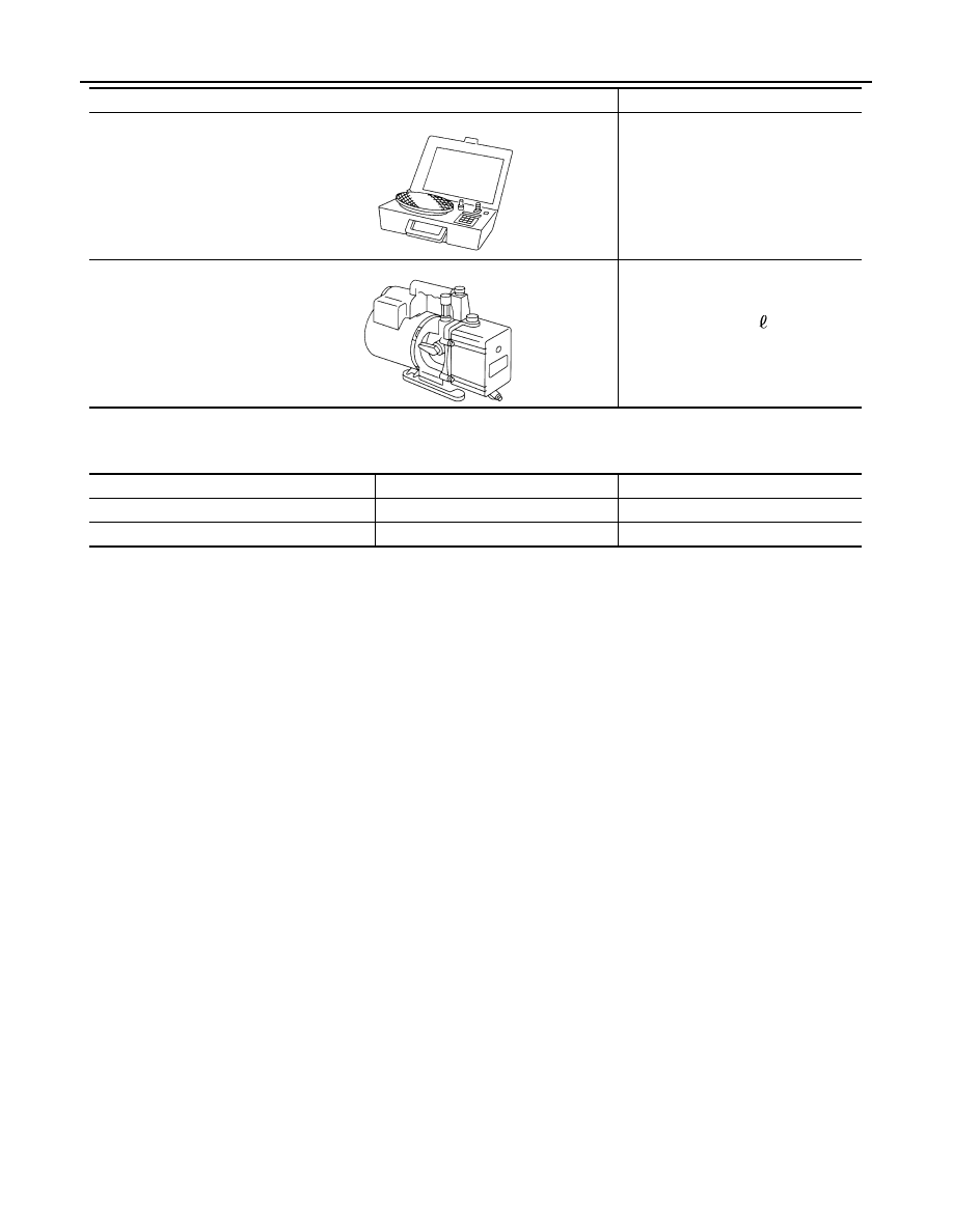
Refrigerant weight scale

For measuring of refrigerant
Fitting size: Thread size
1/2

-16 ACME

Vacuum pump
(Including the isolator valve)

Capacity:
• Air displacement: 4 CFM
• Micron rating: 20 microns
• Oil capacity: 482 m  (17 Imp fl oz.)
Fitting size: Thread size
• 1/2

-16 ACME

Tool name

Description

S-NT200

S-NT203

Name

Application

Note

Refrigerant can (HFC-134a)

Charging refrigerant

Compressor oil (ND-OIL11)

Refilling compressor oil

COMPONENT PARTS

HA-15

< SYSTEM DESCRIPTION >

[WITH HEAT PUMP SYSTEM]

C

D

E

F

G

H

J

K

L

M

A

B

HA

N

O

P

SYSTEM DESCRIPTION

COMPONENT PARTS

REFRIGERATION SYSTEM
REFRIGERATION SYSTEM : Component Parts Location

INFOID:0000000010122088

COMPONENT PARTS LOCATION

COMPONENT PARTS DESCRIPTION

A.

Built-in heating and cooling unit assembly

AWIIA1658ZZ

No.

Location

DESCRIPTION

1.

3-way valve

Controls refrigerant flow for cooling or heating applications.

2.

2-way valve

Controls refrigerant flow for cooling or heating applications.

3.

Accumulator

Refer to 

HA-19, "Accumulator"

.

4.

Condenser

Cools the high-temperature high-pressure refrigerant discharged from the compressor to 
change it into a liquid. Refer to 

HA-16, "Condenser"

.

5.

Electric compressor

Performs the intake, compression, and discharge of refrigerant, and circulates the refrigerant in 
the cooler cycle. Refer to 

HA-17, "Electric Compressor"

.

6.

PTC heater

Provides heated air.

HA-16

< SYSTEM DESCRIPTION >

[WITH HEAT PUMP SYSTEM]

COMPONENT PARTS

HEATING AND COOLING UNIT ASSEMBLY
HEATING AND COOLING UNIT ASSEMBLY : Heating and Cooling Unit

INFOID:0000000010122089

This unit combines the blower unit, heating unit, and cooling unit into

an assembly.

HEATING AND COOLING UNIT ASSEMBLY : Evaporator

INFOID:0000000010122090

A thin laminate pipeless evaporator is used.

HEATING AND COOLING UNIT ASSEMBLY : Inner condenser

INFOID:0000000010122091

An aluminum corrugated fin inner condenser is used.

Condenser

INFOID:0000000010122092

DESCRIPTION

A parallel-flow condenser with a sub-cool cycle is used.

STRUCTURE AND OPERATION

7.

Evaporator

The misty liquid refrigerant causes evaporation and turns into gas by the air blown from blower 
motor. Cools the air by vaporization heat at this time. Refer to 

HA-16, "HEATING AND COOLING 

UNIT ASSEMBLY : Evaporator"

.

8.

Inner Condenser

The refrigerant gas condenses into liquid by the air blown from blower motor. Released heat 
warms the air by condensation at this time. Refer to 

HA-16, "HEATING AND COOLING UNIT 

ASSEMBLY : Inner condenser"

.

No.

Location

DESCRIPTION

JMIIA2578ZZ

JSIIA0295GB

JMIIA2579ZZ

COMPONENT PARTS

HA-17

< SYSTEM DESCRIPTION >

[WITH HEAT PUMP SYSTEM]

C

D

E

F

G

H

J

K

L

M

A

B

HA

N

O

P

The sub-cool section further cools the liquid refrigerant, increasing the amount of heat that the liquid refriger-

ant can absorb and improving cooling performance.

Electric Compressor

INFOID:0000000010122093

• An electric scroll compressor is used.
• A 3-phase output inverter with IPM

Note

 is used.

• The inverter is adopted to IPM

Note

 for smaller size and improved

reliability.

NOTE:

IPM (Intelligent Power Module) is the element which delivered

power device equivalent to IGBT and the protection feature of the

circuit to one package.

NOTE:

IGBT (Insulated Gate Bipolar Transistor) is a transistor which is

suitable for high voltages and large currents and which can control

large electrical power using a small gate voltage.

• The structure integrates the inverter, compressor, and motor, allowing compressor to operate at any speed.

AWIIA1659ZZ

JMIIA2581ZZ


Content   ..  721  722  723  724   ..