Nissan Leaf. Manual - part 709


  Index      Nissan     Nissan Leaf (2011-2014 year) - Service and Repair Manual


Search            


Content   ..  707  708  709  710   ..


Nissan Leaf. Manual - part 709


GI-48

< PRECAUTION >

PROCEDURE FOR PARK LOCK RELEASE
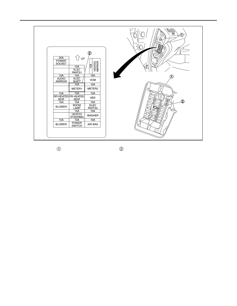
• METER 1

4. Release parking brake.
5. Turn power switch OFF. (Release brake pedal)
6. Move the vehicle while power switch is OFF. 
7. Fix the vehicle after moving. (Using parking brake or tire stopper)
8. Install fuse that is removed. 
9. Turn power switch ON (Press switch twice without depressing brake pedal) and wait for 5 seconds at this

moment, maintain the shift position to the N position. (Charge 12V battery if its voltage is low)

10. Turn power switch OFF. (Wait for 5 seconds)

Fuse block

METER 1 fuse

JMAIA1125ZZ

SERVICE INFORMATION FOR ELECTRICAL INCIDENT

GI-49

< BASIC INSPECTION >

C

D

E

F

G

H

I

J

K

L

M

B

GI

N

O

P

BASIC INSPECTION

SERVICE INFORMATION FOR ELECTRICAL INCIDENT

Work Flow

INFOID:0000000010122929

WORK FLOW

Control Units and Electrical Parts

INFOID:0000000010122930

PRECAUTIONS

• Never reverse polarity of battery terminals.

• Install only parts specified for a vehicle.

• Before replacing the control unit, check the input and output and functions of the component parts. 

• Do not apply excessive force when disconnecting a connector.

SGI838

STEP

DESCRIPTION

STEP 1

Get detailed information about the conditions and the environment when the incident occurred.
The following are key pieces of information required to make a good analysis:

WHAT

Vehicle Model, Engine, Transmission/Transaxle and the System (i.e. Radio).

WHEN

Date, Time of Day, Weather Conditions, Frequency.

WHERE

Road Conditions, Altitude and Traffic Situation.

HOW

System Symptoms, Operating Conditions (Other Components Interaction). 
Service History and if any After Market Accessories have been installed. 

STEP 2

Operate the system, road test if necessary.
Verify the parameter of the incident.
If the problem cannot be duplicated, refer to “Incident Simulation Tests”.

STEP 3

Get the proper diagnosis materials together including:
• Power Supply Routing
• System Operation Descriptions
• Applicable Service Manual Sections
• Check for any Service Bulletins
Identify where to begin diagnosis based upon your knowledge of the system operation and the customer comments.

STEP 4

Inspect the system for mechanical binding, loose connectors or wiring damage.
Determine which circuits and components are involved and diagnose using the Power Supply Routing and Harness Lay-
outs.

STEP 5

Repair or replace the incident circuit or component.

STEP 6

Operate the system in all modes. Verify the system works properly under all conditions. Check you have not inadvert-
ently created a new incident during your diagnosis or repair steps.

GI-50

< BASIC INSPECTION >

SERVICE INFORMATION FOR ELECTRICAL INCIDENT

• Do not apply excessive shock to the control unit by dropping or hit-

ting it.

• Be careful to prevent condensation in the control unit due to rapid

temperature changes and do not let water or rain get on it. If water

is found in the control unit, dry it fully and then install it in the vehi-

cle.

• Be careful not to let oil to get on the control unit connector.

• Avoid cleaning the control unit with volatile oil.

• Do not disassemble the control unit, and do not remove the upper

and lower covers.

• When using a DMM, be careful not to let test probes get close to

each other to prevent the power transistor in the control unit from

damaging battery voltage because of short circuiting.

• When checking input and output signals of the control unit, use the

specified check adapter.

How to Check Terminal

INFOID:0000000010122931

HARNESS REPAIR KIT

• Use the harness repair kit J-48817 shown below when replacing connectors or terminals.

• The harness repair kit contains some of the most commonly used NISSAN/INFINITI connectors and termi-

nals. For detailed connector and terminal pin replacement procedures, refer to the J-48817 User Guide.

HOW TO PROBE CONNECTORS

SAIA0255E

JMCIA0152GB

Tool number

(TechMate No.)

Tool name

Description

-
(J-48817)
Harness repair kit

ALAIA0137ZZ

SERVICE INFORMATION FOR ELECTRICAL INCIDENT

GI-51

< BASIC INSPECTION >

C

D

E

F

G

H

I

J

K

L

M

B

GI

N

O

P

• Connector damage and an intermittent connection can result from improperly probing of the connector dur-

ing circuit checks.

• The probe of a digital multimeter (DMM) may not correctly fit the connector cavity. To correctly probe the

connector, follow the procedures below using a “T” pin. For the best contact grasp the “T” pin using an alliga-

tor clip.

Probing from Harness Side 

Standard type (not waterproof type) connector should be probed

from harness side with “T” pin.

• If the connector has a rear cover such as a ECM connector,

remove the rear cover before probing the terminal.

• Do not probe waterproof connector from harness side. Damage to

the seal between wire and connector may result.

Probing from Terminal Side 

FEMALE TERMINAL

• There is a small notch above each female terminal. Probe each

terminal with the “T” pin through the notch.

Do not insert any object other than the same type male terminal

into female terminal.

• Some connectors do not have a notch above each terminal. To

probe each terminal, remove the connector retainer to make con-

tact space for probing.

MALE TERMINAL

• Carefully probe the contact surface of each terminal using a “T”

pin.

CAUTION:

Never bend terminal.

How to Check Enlarged Contact Spring of Terminal

SGI841

SEL265V

SEL266V

SEL267V


Content   ..  707  708  709  710   ..