Nissan Leaf. Manual - part 588


  Index      Nissan     Nissan Leaf (2011-2014 year) - Service and Repair Manual


Search            


Content   ..  586  587  588  589   ..


Nissan Leaf. Manual - part 588


EVC-376

< DTC/CIRCUIT DIAGNOSIS >

CHARGING CONNECTOR LOCK RELAY

CHARGING CONNECTOR LOCK RELAY

Diagnosis Procedure

INFOID:0000000010120836

1.

CHECK FUSE

1. Turn power switch OFF.

2. Pull out #43 fuse.

3. Check that the fuse is not fusing.
Is the inspection result normal?

YES

>> GO TO 2.

NO

>> Replace the fuse after repairing the applicable circuit.

2.

CHECK CHARGE CONNECTOR LOCK RELAY OUTPUT VOLTAGE

1. Insert the fuse which pulled put.

2. Press charge connector lock switch at the “OFF” position.

3. Connect EVSE.

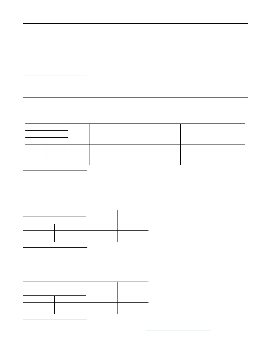
4. Check the voltage between IPDM E/R harness connector and ground under the following conditions.

Is the inspection result normal?

YES

>> GO TO 8.

NO

>> GO TO 3.

3.

CHECK 12V BATTERY POWER SUPPLY-1

1. Disconnect EVSE.

2. Check the voltage between IPDM E/R harness connector and ground.

Is the inspection result normal?

YES

>> GO TO 6.

NO

>> GO TO 4.

4.

12V BATTERY POWER SUPPLY-2

Check the voltage between IPDM E/R harness connector and ground.

Is the inspection result normal?

YES

>> GO TO 5.

NO

>> Check IPDM E/R power supply circuit. Refer to 

PCS-28, "Diagnosis Procedure"

.

+

Condition

Voltage

IPDM E/R

Connector

Terminal

E14

35

Ground

• Power switch: OFF
• Selector lever: P range
• Immediately after the charge connector lock switch 

is pressed to “LOCK” position.

12V battery voltage

+

Voltage

IPDM E/R

Connector

Terminal

E14

41

Ground

12V battery volt-

age

+

Voltage

IPDM E/R

Connector

Terminal

E9

2

Ground

12V battery volt-

age

CHARGING CONNECTOR LOCK RELAY

EVC-377

< DTC/CIRCUIT DIAGNOSIS >

D

E

F

G

H

I

J

K

L

M

A

B

EVC

N

O

P

5.

CHECK CHARGE CONNECTOR LOCK RELAY DRIVE CIRCUIT

1. Disconnect VCM harness connector.

2. Check harness for short to ground, between IPDM E/R harness connector and VCM harness connector.

Is the inspection result normal?

YES

>> Replace IPDM E/R. Refer to 

PCS-29, "Removal and Installation"

.

NO

>> Repair or replace error-detected parts.

6.

CHECK CHARGE CONNECTOR LOCK RELAY DRIVE CIRCUIT

1. Disconnect VCM harness connector.

2. Check the continuity between IPDM E/R harness connector and VCM harness connector.

3. Also check harness for short to ground and short to power.
Is the inspection result normal?

YES

>> GO TO 7.

NO

>> Repair or replace error-detected parts.

7.

CHECK VCM GROUND CIRCUIT

Check the continuity between VCM harness connector and ground.

Is the inspection result normal?

YES

>> Check intermittent incident. Refer to 

GI-53, "Intermittent Incident"

.

NO

>> Repair or replace error-detected parts.

8.

CHECK CHARGE CONNECTOR LOCK RELAY OUTPUT CIRCUIT

1. Disconnect EVSE.

2. Disconnect VCM harness connector.

3. Check the continuity between IPDM E/R harness connector and VCM harness connector.

4. Also check harness for short to ground and short to power.
Is the inspection result normal?

+

Continuity

IPDM E/R

Connector

Terminal

E14

41

Ground

Not existed

+

Continuity

IPDM E/R

VCM

Connector

Terminal

Connector

Terminal

E14

41

E123

78

Existed

+

Continuity

VCM

Connector

Terminal

E61

58

Ground

Existed

65

E62

118

126

+

Continuity

IPDM E/R

VCM

Connector

Terminal

Connector

Terminal

E14

35

E123

104

Existed

EVC-378

< DTC/CIRCUIT DIAGNOSIS >

CHARGING CONNECTOR LOCK RELAY

YES

>> INSPECTION END

NO

>> Repair or replace error-detected parts.

CHARGE PORT LID OPENER RELAY

EVC-379

< DTC/CIRCUIT DIAGNOSIS >

D

E

F

G

H

I

J

K

L

M

A

B

EVC

N

O

P

CHARGE PORT LID OPENER RELAY

Diagnosis Procedure

INFOID:0000000010120837

1.

CHECK CHARGE PORT LID OPENER ACTUATOR RELAY POWER SUPPLY-1

1. Turn power switch OFF.

2. Disconnect charge port lid opener actuator relay.

3. Check the voltage between charge port lid opener actuator relay harness connector and ground.

Is the inspection result normal?

YES

>> GO TO 6.

NO

>> GO TO 2.

2.

CHECK CHARGE PORT LID OPENER ACTUATOR RELAY POWER SUPPLY-2

Check the voltage between IPDM E/R harness connector and ground.

Is the inspection result normal?

YES

>> GO TO 5.

NO

>> GO TO 3.

3.

CHECK IPDM E/R POWER SUPPLY

Check the voltage between IPDM E/R harness connector and ground.

Is the inspection result normal?

YES

>> GO TO 4.

NO

>> Check 12V battery power supply circuit.

4.

CHECK FUSE

1. Pull out #43 fuse.

2. Check that the fuse is not fusing.
Is the inspection result normal?

YES

>> Replace IPDM E/R. Refer to 

PCS-29, "Removal and Installation"

.

NO

>> Replace the fuse after repairing the applicable circuit.

5.

CHECK CHARGE PORT LID OPENER ACTUATOR RELAY POWER SUPPLY CIRCUIT

1. Disconnect IPDM E/R harness connector.

2. Check the continuity between IPDM E/R harness connector and charge port lid opener actuator relay har-

ness connector.

+

Voltage

Charge port lid opener actuator re-

lay

Connector

Terminal

E127

5

Ground

12V battery volt-

age

+

Voltage

IPDM E/R

Connector

Terminal

E14

42

Ground

12V battery volt-

age

+

Voltage

IPDM E/R

Connector

Terminal

E9

2

Ground

12V battery volt-

age


Content   ..  586  587  588  589   ..