Nissan Leaf. Manual - part 587


  Index      Nissan     Nissan Leaf (2011-2014 year) - Service and Repair Manual


Search            


Content   ..  585  586  587  588   ..


Nissan Leaf. Manual - part 587


EVC-372

< DTC/CIRCUIT DIAGNOSIS >

M/C RELAY

NO

>> Replace M/C relay.

6.

CHECK M/C RELAY CONTROL SIGNAL CIRCUIT

1. Turn power switch OFF.

2. Disconnect VCM harness connector.

3. Check the continuity between M/C relay harness connector and VCM harness connector.

4. Also check harness for short to ground and short to power.
Is the inspection result normal?

YES

>> GO TO 7.

NO

>> Repair or replace error-detected parts.

7.

CHECK VCM GROUND CIRCUIT

Check the continuity between VCM harness connector and ground.

Is the inspection result normal?

YES

>> INSPECTION END

NO

>> Repair or replace error-detected parts.

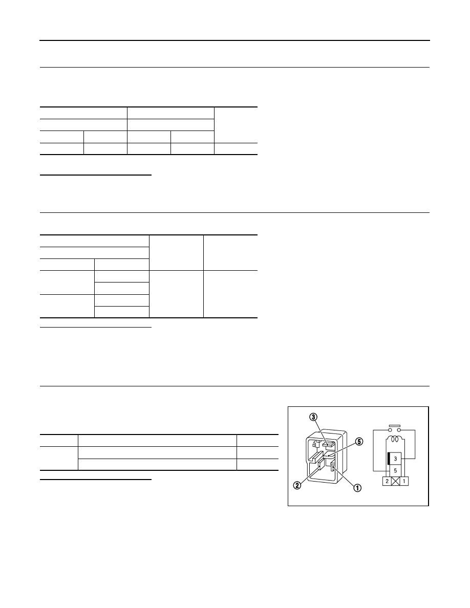
Component Inspection (M/C Relay)

INFOID:0000000010120833

1.

CHECK M/C RELAY

1. Turn power switch OFF.

2. Remove M/C relay.

3. Check the continuity between M/C relay terminals under the fol-

lowing conditions.

Is the inspection result normal?

YES

>> INSPECTION END

NO

>> Replace M/C relay.

+

Continuity

M/C relay

VCM

Connector

Terminal

Connector

Terminal

E65

1

E62

88

Existed

+

Continuity

VCM

Connector

Terminal

E61

58

Ground

Existed

65

E62

118

126

Terminals

Conditions

Continuity

3 and 5

12 V direct current supply between terminals 1 and 2

Existed

No current supply

Not existed

PIIA2636J

F/S CHG RELAY

EVC-373

< DTC/CIRCUIT DIAGNOSIS >

D

E

F

G

H

I

J

K

L

M

A

B

EVC

N

O

P

F/S CHG RELAY

Diagnosis Procedure

INFOID:0000000010120834

1.

CHECK F/S CHG RELAY POWER SUPPLY-1

1. Turn power switch OFF.

2. Remove F/S CHG relay.

3. Turn power switch ON.

4. Check the voltage between F/S CHG relay harness connector and ground.

Is the inspection result normal?

YES

>> GO TO 4.

NO

>> GO TO 2.

2.

CHECK F/S CHG RELAY POWER SUPPLY-2

Check the voltage between IPDM E/R harness connector and ground.

Is the inspection result normal?

YES

>> GO TO 3.

NO

>> Check F/S relay routing circuit. Refer to 

EVC-331, "Diagnosis Procedure"

.

3.

CHECK F/S CHG RELAY POWER SUPPLY CIRCUIT

1. Turn power switch OFF.

2. Disconnect IPDM E/R harness connector.

3. Check the continuity between F/S CHG relay harness connector and IPDM E/R harness connector.

4. Also check harness for short to ground and short to power.
Is the inspection result normal?

YES

>> Check intermittent incident. Refer to 

GI-53, "Intermittent Incident"

.

NO

>> Repair or replace error-detected parts.

4.

CHECK 12V BATTERY POWER SUPPLY-1

Check the voltage between F/S CHG relay harness connector and ground.

+

Voltage

F/S CHG relay

Connector

Terminal

E64

2

Ground

12V battery volt-

age

+

Voltage

IPDM E/R

Connector

Terminal

E15

55

Ground

12V battery volt-

age

+

Continuity

F/S CHG relay

IPDM E/R

Connector

Terminal

Connector

Terminal

E64

2

E15

55

Existed

EVC-374

< DTC/CIRCUIT DIAGNOSIS >

F/S CHG RELAY

Is the inspection result normal?

YES

>> GO TO 8.

NO

>> GO TO 5.

5.

CHECK FUSE

1. Turn power switch OFF.

2. Pull out #33 fuse.

3. Check that the fuse is not fusing.
Is the inspection result normal?

YES

>> GO TO 6.

NO

>> Replace the fuse after repairing the applicable circuit.

6.

CHECK 12V BATTERY POWER SUPPLY-2

Check the voltage between #33 fuse harness connector and ground.

Is the inspection result normal?

YES

>> GO TO 7.

NO

>> Check power supply circuit for battery power supply.

7.

CHECK 12V BATTERY POWER SUPPLY CIRCUIT

1. Check the continuity between F/S CHG relay harness connector and #33 fuse harness connector.

2. Also check harness for short to ground and short to power.
Is the inspection result normal?

YES

>> Check intermittent incident. Refer to 

GI-53, "Intermittent Incident"

.

NO

>> Repair or replace error-detected parts.

8.

CHECK F/S CHG RELAY

Check F/S CHG relay. Refer to 

EVC-375, "Component Inspection (F/S CHG Relay)"

.

Is the inspection result normal?

YES

>> GO TO 9.

NO

>> Replace F/S CHG relay.

9.

CHECK F/S CHG RELAY CONTROL SIGNAL CIRCUIT

1. Turn power switch OFF.

2. Disconnect VCM harness connector.

3. Check the continuity between F/S CHG relay harness connector and VCM harness connector.

+

Voltage

F/S CHG relay

Connector

Terminal

E64

3

Ground

12V battery volt-

age

+

Voltage

#33 fuse terminal

Ground

12V battery voltage

+

Continuity

F/S CHG relay

Connector

Terminal

#33 fuse termi-

nal

E64

3

Existed

F/S CHG RELAY

EVC-375

< DTC/CIRCUIT DIAGNOSIS >

D

E

F

G

H

I

J

K

L

M

A

B

EVC

N

O

P

4. Also check harness for short to ground and short to power.
Is the inspection result normal?

YES

>> GO TO 10.

NO

>> Repair or replace error-detected parts.

10.

CHECK VCM GROUND CIRCUIT

Check the continuity between VCM harness connector and ground.

Is the inspection result normal?

YES

>> INSPECTION END

NO

>> Repair or replace error-detected parts.

Component Inspection (F/S CHG Relay)

INFOID:0000000010120835

1.

CHECK F/S CHG RELAY

1. Turn power switch OFF.

2. Remove F/S CHG relay.

3. Check the continuity between F/S CHG relay terminals under

the following conditions.

Is the inspection result normal?

YES

>> INSPECTION END

NO

>> Replace F/S CHG relay.

+

Continuity

F/S CHG relay

VCM

Connector

Terminal

Connector

Terminal

E64

1

E61

8

Existed

+

Continuity

VCM

Connector

Terminal

E61

58

Ground

Existed

65

E62

118

126

Terminals

Conditions

Continuity

3 and 5

12 V direct current supply between terminals 1 and 2

Existed

No current supply

Not existed

PIIA2636J


Content   ..  585  586  587  588   ..