Nissan Leaf. Manual - part 582
EVC-352
< DTC/CIRCUIT DIAGNOSIS >
P31E5 VCM POWER SUPPLY
NO
>> Repair or replace error-detected parts.
4.
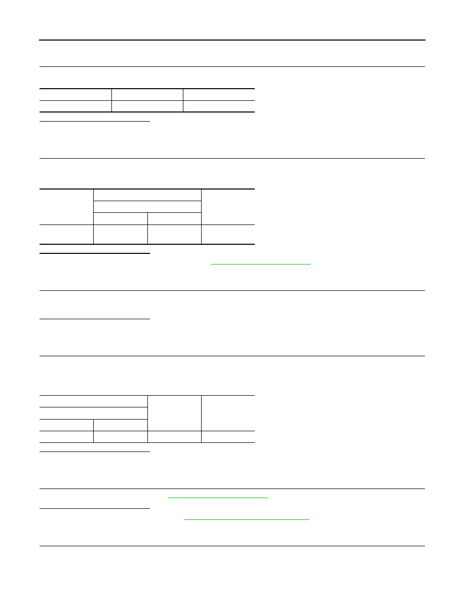
CHECK 12V BATTERY POWER SUPPLY
Check the voltage between #77 fuse terminal and ground.
Is the inspection result normal?
YES
>> GO TO 5.
NO
>> Perform trouble diagnosis for 12V battery power supply.
5.
CHECK 12V BATTERY POWER SUPPLY CIRCUIT
1. Disconnect VCM harness connector.
2. Check the continuity between #77 fuse terminal and VCM harness connector.
Is the inspection result normal?
YES
>> Check intermittent incident. Refer to
GI-53, "Intermittent Incident"
.
NO
>> Repair or replace error-detected parts.
6.
CHECK FUSE
1. Turn power switch ON.
2. Pull out #43 fuse and check that the fuse is not fusing.
Is the inspection result normal?
YES
>> GO TO 9.
NO
>> GO TO 7.
7.
CHECK 12V BATTERY POWER SUPPLY CIRCUIT
1. Disconnect IPDM E/R harness connector.
2. Disconnect VCM harness connector.
3. Check harness for short to ground, between IPDM E/R harness connector and VCM harness connector.
Is the inspection result normal?
YES
>> GO TO 8.
NO
>> Repair or replace error-detected parts.
8.
CHECK INTERMITTENT INCIDENT
Check intermittent incident. Refer to
GI-53, "Intermittent Incident"
.
Is the inspection result normal?
YES
>> Replace IPDM E/R. Refer to
PCS-29, "Removal and Installation"
NO
>> Repair or replace error-detected parts.
9.
CHECK 12V BATTERY POWER SUPPLY-1
1. Insert the fuse which pulled out.
2. Check the voltage between IPDM E/R harness connector and ground.
+
−
Voltage
#77 fuse terminal
Ground
12V battery voltage
+
−
Continuity
VCM
Connector
Terminal
#77 fuse termi-
nal
E62
79
Existed
+
−
Continuity
IPDM E/R
Connector
Terminal
E14
42
Ground
Not existed