Nissan Leaf. Manual - part 541
EVC-188
< DTC/CIRCUIT DIAGNOSIS >
P1550, P1551, P1552 BATTERY CURRENT SENSOR
Component Inspection
INFOID:0000000010120638
1.
CHECK BATTERY CURRENT SENSOR
1. Turn power switch OFF.
2. Reconnect harness connectors disconnected.
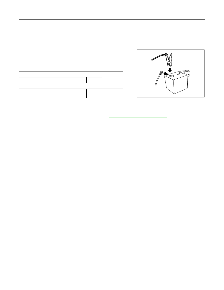
3. Disconnect battery negative cable.
4. Install jumper cable between battery negative terminal and body
ground.
5. Turn power switch ON.
6. Check the voltage between VCM harness connector terminals.
Before measuring the terminal voltage, confirm that the battery is fully charged. Refer to
PG-83, "How to Handle 12V Battery"
.
Is the inspection result normal?
YES
>> INSPECTION END
NO
>> Replace battery current sensor. Refer to
PG-93, "Removal and Installation"
.
VCM
Voltage
(Approx.)
Connector
+
-
Terminal
E62
95
(Battery current sensor signal)
120
2.5 V
JPBIA3286ZZ