Nissan Leaf. Manual - part 530


  Index      Nissan     Nissan Leaf (2011-2014 year) - Service and Repair Manual


Search            


Content   ..  528  529  530  531   ..


Nissan Leaf. Manual - part 530


EVC-144

< DTC/CIRCUIT DIAGNOSIS >

P0A00 COOLANT TEMPERATURE SENSOR

Is the inspection result normal?

YES

>> GO TO 3.

NO

>> GO TO 5.

3.

CHECK COOLANT TEMPERATURE SENSOR GROUND CIRCUIT

1. Turn power switch OFF.

2. Disconnect VCM harness connector.

3. Check the continuity between VCM harness connector and coolant temperature sensor harness connec-

tor.

Is the inspection result normal?

YES

>> GO TO 4.

NO

>> Repair or replace error-detected parts.

4.

CHECK VCM GROUND CIRCUIT

Check the continuity between VCM harness connector and ground.

Is the inspection result normal?

YES

>> GO TO 8.

NO

>> Repair or replace error-detected parts.

5.

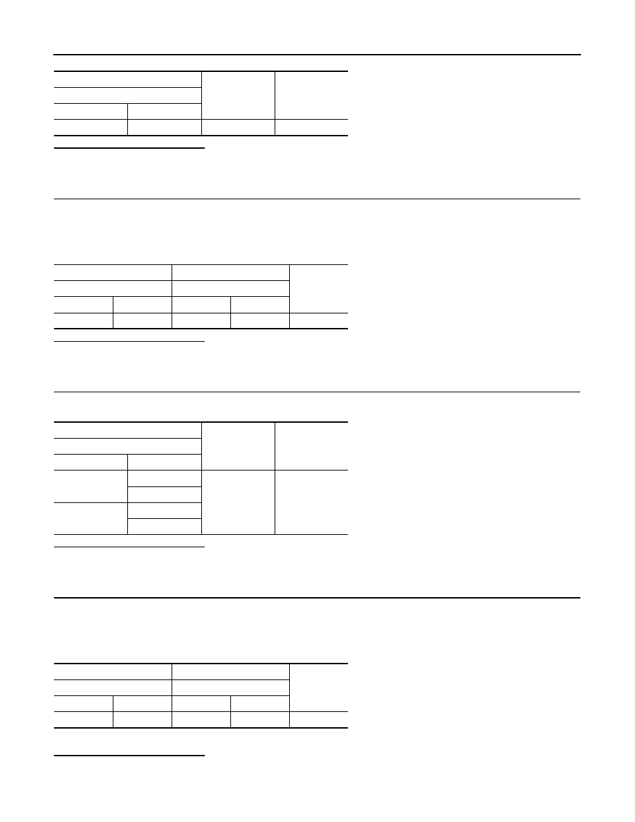
CHECK SENSOR POWER SUPPLY CIRCUIT

1. Turn power switch OFF.

2. Disconnect VCM harness connector.

3. Check the continuity between VCM harness connector and coolant temperature sensor harness connec-

tor.

4. Also check harness for short to ground and short to power.
Is the inspection result normal?

YES

>> GO TO 6.

NO

>> Repair or replace error-detected parts.

+

Voltage

(Approx.)

Coolant temperature sensor

Connector

Terminal

E69

1

Ground

5 V

+

Continuity

VCM

Coolant temperature sensor

Connector

Terminal

Connector

Terminal

E62

121

E69

2

Existed

+

Continuity

VCM

Connector

Terminal

E61

58

Ground

Existed

65

E63

118

126

+

Continuity

VCM

Coolant temperature sensor

Connector

Terminal

Connector

Terminal

E62

110

E69

1

Existed

P0A00 COOLANT TEMPERATURE SENSOR

EVC-145

< DTC/CIRCUIT DIAGNOSIS >

D

E

F

G

H

I

J

K

L

M

A

B

EVC

N

O

P

6.

CHECK VCM POWER SUPPLY CIRCUIT

Check VCM power supply circuit. Refer to 

EVC-138, "VCM : Diagnosis Procedure"

.

Is the inspection result normal?

YES

>> GO TO 8.

NO

>> Repair or replace error-detected parts.

7.

CHECK COOLANT TEMPERATURE SENSOR

Check coolant temperature sensor. Refer to 

EVC-145, "Component Inspection"

.

Is the inspection result normal?

YES

>> Check intermittent incident. Refer to 

GI-53, "Intermittent Incident"

.

NO

>> Replace coolant temperature sensor. Refer to 

HCO-14, "Exploded View"

.

8.

CHECK INTERMITTENT INCIDENT

Check intermittent incident. Refer to 

GI-53, "Intermittent Incident"

.

Is the inspection result normal?

YES

>> Replace VCM. Refer to 

EVC-423, "Removal and Installation"

.

NO

>> Repair or replace error-detected parts.

Component Inspection

INFOID:0000000010120611

1.

CHECK COOLANT TEMPERATURE SENSOR

1. Turn power switch OFF.

2. Disconnect coolant temperature sensor harness connector.

3. Remove coolant temperature sensor.

4. Check resistance between coolant temperature sensor termi-

nals by heating with hot water as shown in the figure.

Is the inspection result normal?

YES

>> INSPECTION END

NO

>> Replace coolant temperature sensor. Refer to 

HCO-14,

"Exploded View"

.

Terminals

Condition

Resistance

1 and 2

Temperature [

°C (°F)]

20 (68)

2.35 - 2.73 k

50 (122)

0.68 - 1.00 k

90 (194)

0.236 - 0.260 k

JMBIA0080ZZ

EVC-146

< DTC/CIRCUIT DIAGNOSIS >

P0A0B HIGH VOLTAGE CONNECTOR INTERLOCK DETECT CIRCUIT

P0A0B HIGH VOLTAGE CONNECTOR INTERLOCK DETECT CIRCUIT

Description

INFOID:0000000010120612

The connection detecting circuit is used to detect the connection status of the PDM (Power Delivery Module)

cover and the bus bar cover of PDM (Power Delivery Module). 

The connection detecting circuit consists of two circuits (i.e. power supply circuit and signal input circuit).

When the PDM (Power Delivery Module) cover and the bus bar cover are installed normally, their protrusions

press the internal switch of PDM (Power Delivery Module). Accordingly, the connection detecting circuit is

energized and a voltage signal is input.

DTC Logic

INFOID:0000000010120613

DTC DETECTION LOGIC

DTC CONFIRMATION PROCEDURE

1.

PRECONDITIONING

• Turn power switch OFF and wait at least 90 seconds.

CAUTION:

During this period, never perform vehicle handling such as opening and closing of doors. If some

kind of vehicle handling is performed, then wait another 90 seconds or more from the time of the

vehicle handling.

• Make sure that 12V battery voltage is 11 V or more.

>> GO TO 2.

2.

PERFORM DTC CONFIRMATION PROCEDURE

With CONSULT

1. Turn power switch ON.

2. Turn power switch OFF and wait at least 90 seconds.

CAUTION:

During this period, never perform vehicle handling such as opening and closing of doors. If some

kind of vehicle handling is performed, then wait another 90 seconds or more from the time of the

vehicle handling.

3. Turn power switch ON and wait at least 5 seconds.

4. Check self-diagnostic result.
Is DTC detected?

YES

>> Proceed to 

EVC-146, "Diagnosis Procedure"

.

NO

>> INSPECTION END

Diagnosis Procedure

INFOID:0000000010120614

DANGER:

Since hybrid vehicles and electric vehicles contain a high voltage battery, there is the risk of

electric shock, electric leakage, or similar accidents if the high voltage component and vehicle are

handled incorrectly. Be sure to follow the correct work procedures when performing inspection and

maintenance.

WARNING:

• Be sure to remove the service plug in order to disconnect the high voltage circuits before perform-

ing inspection or maintenance of high voltage system harnesses and parts.

DTC

CONSULT screen terms

(Trouble diagnosis content)

DTC detecting condition

Possible cause

P0A0B

HV SYSTEM INTERLOCK 
ERROR
(High voltage system inter-
lock circuit performance)

VCM detects that high voltage harness con-
nector interlock circuit voltage remains ex-
cessively high for 0.5 seconds or more 
immediately before M/C relay turns ON. 

• Harness or connectors
• VCM
• PDM (Power Delivery Module)

P0A0B HIGH VOLTAGE CONNECTOR INTERLOCK DETECT CIRCUIT

EVC-147

< DTC/CIRCUIT DIAGNOSIS >

D

E

F

G

H

I

J

K

L

M

A

B

EVC

N

O

P

• To prevent the removed service plug from being connected by mistake during the procedure, always

carry it in your pocket or put it in the tool box.

• Be sure to wear insulating protective equipment consisting of glove, shoes, face shield and glasses

before beginning work on the high voltage system.

• Clearly identify the persons responsible for high voltage work and ensure that other persons do not

touch the vehicle. When not working, cover high voltage parts with an insulating cover sheet or sim-

ilar item to prevent other persons from contacting them.

• Refer to 

EVC-10, "High Voltage Precautions"

.

CAUTION:

• Never bring the vehicle into the READY status with the service plug removed unless otherwise

instructed in the Service Manual. A malfunction may occur if this is not observed.

• Erase DTC after the work is completed.

1.

OVERALL FUNCTION CHECK

With CONSULT

1. On the CONSULT screen, select “EV/HEV” >> “DATA MONITOR” >> “HV INTERLOCK (DC/DC)”.

2. Check that “On” is displayed.
Is the inspection result normal?

YES

>> Check intermittent incident. Refer to 

GI-53, "Intermittent Incident"

.

NO

>> GO TO 2.

2.

PRECONDITIONING

WARNING:

Disconnect high voltage. Refer to 

GI-33, "How to Disconnect High Voltage"

.

Check voltage in high voltage circuit. (Check that condenser are discharged.)

1. Lift up the vehicle and remove the Li-ion battery under covers. Refer to 

EVB-181, "Exploded View"

.

2. Disconnect high voltage harness connector and PTC heater harness connector from front side of Li-ion

battery. Refer to 

EVB-181, "Removal and Installation"

.

3. Measure voltage between high voltage harness connector terminals and PTC heater harness connector

terminals.

DANGER:


 Touching high voltage components without using the appropriate protective equipment will

cause electrocution.

CAUTION:

For voltage measurements, use a tester which can measure to 500 V or higher.

>> GO TO 3.

3.

CHECK CONNECTION DETECTING CIRCUIT POWER SUPPLY

1. Disconnect PDM (Power Delivery Module) harness connector.

2. Reconnect 12V battery negative terminal.

3. Turn power switch ON.

Standard

: 5 V or less 

JPCIA0296ZZ


Content   ..  528  529  530  531   ..