Nissan Leaf. Manual - part 510


  Index      Nissan     Nissan Leaf (2011-2014 year) - Service and Repair Manual


Search            


Content   ..  508  509  510  511   ..


Nissan Leaf. Manual - part 510


EVC-64

< SYSTEM DESCRIPTION >

SYSTEM

AUTOMATIC SPEED CONTROL DEVICE (ASCD) : System Description

INFOID:0000000010120569
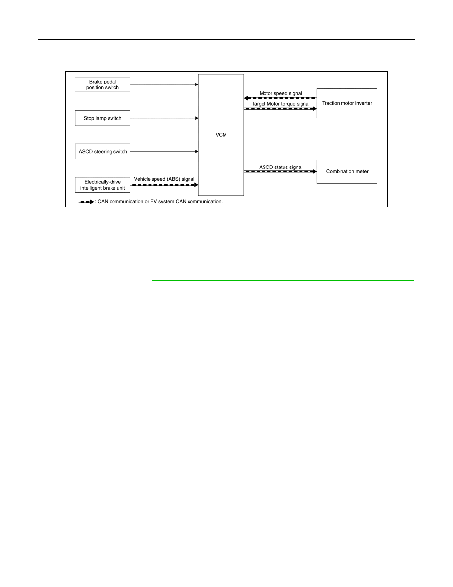
SYSTEM DIAGRAM

BASIC ASCD SYSTEM

Automatic Speed Control Device (ASCD) allows a driver to keep vehicle at a predetermined constant speed

without depressing accelerator pedal. Driver can set vehicle speed in advance between approximately 40 km/

h (25 MPH) and 144 km/h (89 MPH).

VCM controls the traction motor to regulate vehicle speed.

Operation status of ASCD is indicated on the information display in the combination meter. If any malfunction

occurs in ASCD system, it automatically deactivates control.

For the switch function, Refer to 

EVC-69, "AUTOMATIC SPEED CONTROL DEVICE (ASCD) : Switch Name

and Function"

.

For the ASCD indicator, Refer to 

EVC-66, "WARNING/INDICATOR/CHIME LIST : Indicator/Information"

.

CAUTION:

Always drive vehicle in a safe manner according to traffic conditions and obey all traffic laws.

CANCEL OPERATION

When any of following conditions exist, cruise operation is cancelled.

• CANCEL switch is pressed

• More than two switches on ASCD steering switch are pressed at the same time (Set speed is cleared)

• Brake pedal is depressed

• Selector lever position is N, P or R position

• TCS system is operated

When VCM detects malfunction for some self-diagnoses regarding ASCD system, VCM cancels the cruise

operation and informs the driver by blinking SET indicator lamp quickly.

If ASCD MAIN switch is turned to OFF while ASCD is activated, all of ASCD operations are cancelled and

vehicle speed memory is erased.

ECO INDICATOR CONTROL

JSCIA0806GB

SYSTEM

EVC-65

< SYSTEM DESCRIPTION >

D

E

F

G

H

I

J

K

L

M

A

B

EVC

N

O

P

ECO INDICATOR CONTROL : System Description

INFOID:0000000010120570

SYSTEM DIAGRAM

INPUT/OUTPUT SIGNAL CHART

DESCRIPTION

VCM calculates the instantaneous ECO operability based on the driver accelerator operation, brake operation,

vehicle idle time, and air conditioner operation status and displays this in the instant ECO indicator. 

Furthermore, VCM samples the instantaneous ECO operability every second and compares it to the map

stored by VCM to calculate the cumulative ECO drivability, and if this value exceeds the set value, then the

ECO tree segment is illuminates. 

NOTE:

Once the ECO tree segment is illuminated, it does not turn OFF (dim) during the current trip. 

NOTICE:

The idle time is the status when not driving in the READY state. 

For details regarding the ECO indicator functions, refer to 

MWI-27, "ECO INDICATOR : System Description"

.

WARNING/INDICATOR/CHIME LIST
WARNING/INDICATOR/CHIME LIST : Warning lamps/Indicator lamps

INFOID:0000000010120571

JSCIA0175GB

Output sensor/ECU

Signal name

Input ECU/actuator

Signal form

Accelerator pedal position sen-
sor

Accelerator pedal position

VCM

Voltage

A/C auto amp.

Ambient temperature signal

EV system CAN

Air conditioner ON signal

A/C maximum power signal

PTC maximum power signal

Traction motor inverter

Motor speed signal

Regeneration brake torque signal

Electrically-driven intelligent 
brake unit

Target brake force signal

CAN

VCM

ECO indicator signal

Combination meter

ECO tree signal

Item

Design

Reference

EV system warning lamp

For layout, refer to 

MWI-6, "METER SYSTEM : Combination Meter"

.

For function, refer to 

EVC-23, "WARNING LAMPS/INDICATOR LAMPS : EV System 

Warning Lamp"

.

EVC-66

< SYSTEM DESCRIPTION >

SYSTEM

WARNING/INDICATOR/CHIME LIST : Warning Chime

INFOID:0000000010120572

WARNING/INDICATOR/CHIME LIST : Warning/Indicator (On Information Display)

INFOID:0000000010120573

WARNING/INDICATOR/CHIME LIST : Indicator/Information

INFOID:0000000010120574

 ASCD INDICATOR

Low battery charge warning 
lamp

For layout, refer to 

MWI-6, "METER SYSTEM : Combination Meter"

.

For function, refer to 

EVC-25, "WARNING LAMPS/INDICATOR LAMPS : Low Bat-

tery Charge Warning Lamp"

.

Plug in indicator lamp

For layout, refer to 

MWI-6, "METER SYSTEM : Combination Meter"

.

For function, refer to 

EVC-26, "WARNING LAMPS/INDICATOR LAMPS : Plug In In-

dicator Lamp"

.

Power limitation indicator lamp

For layout, refer to 

MWI-6, "METER SYSTEM : Combination Meter"

.

For function, refer to 

EVC-28, "WARNING LAMPS/INDICATOR LAMPS : Power 

Limitation Indicator Lamp"

.

Ready to drive indicator lamp

For layout, refer to 

MWI-6, "METER SYSTEM : Combination Meter"

.

For function, refer to 

EVC-29, "WARNING LAMPS/INDICATOR LAMPS : Ready To 

Drive Indicator Lamp"

.

12v battery charge warning lamp

For layout, refer to 

MWI-6, "METER SYSTEM : Combination Meter"

.

For function, refer to 

EVC-31, "WARNING LAMPS/INDICATOR LAMPS : 12V Bat-

tery Charge Warning Lamp"

.

Item

Design

Reference

Item

Reference

DC/DC converter warning chime

Refer to 

EVC-37, "WARNING CHIME : DC/DC Converter Warning Chime"

.

Power switch reminder chime

Refer to 

EVC-39, "WARNING CHIME : Power Switch Reminder Chime"

.

Shift P warning chime

Refer to 

EVC-39, "WARNING CHIME : Shift P Warning Chime"

.

Item

Reference

DC/DC Converter Warning

Refer to 

EVC-32, "WARNING/INDICATOR (ON INFORMATION DISPLAY) : DC/DC 

Converter Warning"

.

Low Battery Charge Warning

Refer to 

EVC-34, "WARNING/INDICATOR (ON INFORMATION DISPLAY) : Low 

Battery Charge Warning"

.

Power Limitation Warning

Refer to 

EVC-35, "WARNING/INDICATOR (ON INFORMATION DISPLAY) : Power 

Limitation Warning"

.

Shift P Warning

Refer to 

EVC-36, "WARNING/INDICATOR (ON INFORMATION DISPLAY) : Shift P 

Warning"

.

SYSTEM

EVC-67

< SYSTEM DESCRIPTION >

D

E

F

G

H

I

J

K

L

M

A

B

EVC

N

O

P

CRUISE indicator
SET indicator

ECO MODE INDICATOR

TIMER SETTING STATUS

Design/Purpose

Various types of information on Climate Ctrl. Timer and timer charge is displayed.

Symbol

Function

EVC-64, "AUTOMATIC SPEED CONTROL DEVICE (ASCD) : System Descrip-
tion"

JSCIA0519ZZ

Symbol

Function

EVC-50, "ECO MODE/B MODE SYSTEM : System Description"

JPNIA1941ZZ

No.

Name

Function

Timer setting (charging and Climate 
Ctrl.) and charge connector lock set-
ting status

The timer settings status (On or Off) and the air conditioning/heater or climate con-
trol and the charge connector lock setting status (AUTO, LOCK or UNLOCK)

Charging timer setting confirmation

The charging timer starting and ending (where fitted) hour, minute and day (where 
fitted) for the next charge time that has been set can be checked. 

JSCIA1052GB


Content   ..  508  509  510  511   ..