Nissan Leaf. Manual - part 506


  Index      Nissan     Nissan Leaf (2011-2014 year) - Service and Repair Manual


Search            


Content   ..  504  505  506  507   ..


Nissan Leaf. Manual - part 506


EVC-48

< SYSTEM DESCRIPTION >

SYSTEM

the signal, VCM activates the system main relay 1 and deactivates the pre-charge relay. Then, normal power

is supplied to the respective systems.
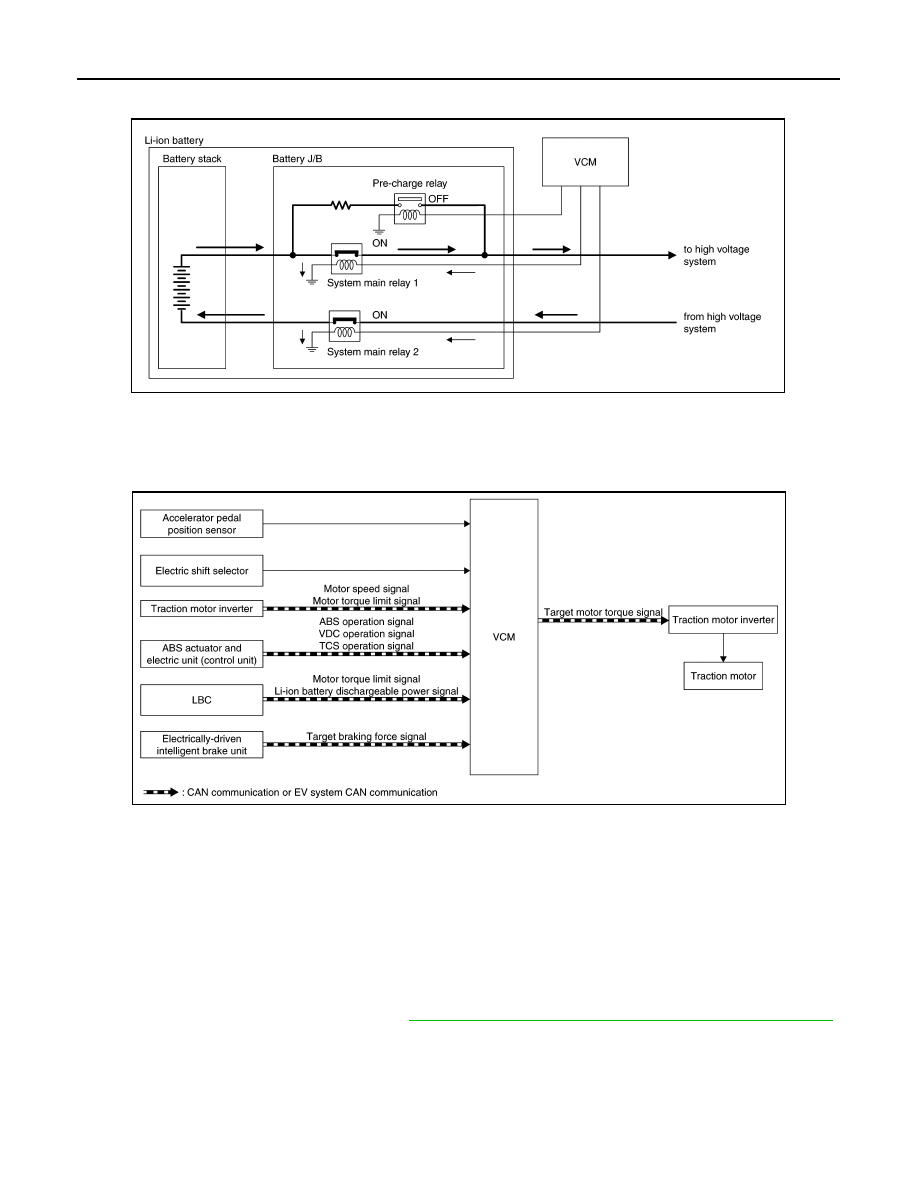
MOTOR POWER CONTROL
MOTOR POWER CONTROL : System Description

INFOID:0000000010120557

SYSTEM DIAGRAM

NOTE:

VCM calculates vehicle speed, based on a motor speed. 

DESCRIPTION

The EV system generates traction force by converting the direct current from the Li-ion battery to an alternat-

ing current by the traction motor inverter and operating the traction motor with the alternating current.

VCM calculates target traction force, based on an accelerator pedal position, vehicle speed, and shift position.

After this, VCM adds creep force to the calculated target traction force.

Subsequently, VCM adds torque limitations to the calculated driving force, based on torque down signals

received from each system, to decide a motor torque request signal.

This motor torque request signal is transmitted to the traction motor inverter via EV system CAN communica-

tion.

For the operation principle of the motor, refer to 

TMS-19, "MOTOR POWER CONTROL : Operating Principle"

.

OUTPUT LIMIT AND OUTPUT STOP REQUEST LIST

JSCIA0493GB

JSCIA0778GB

SYSTEM

EVC-49

< SYSTEM DESCRIPTION >

D

E

F

G

H

I

J

K

L

M

A

B

EVC

N

O

P

MOTOR REGENERATION CONTROL
MOTOR REGENERATION CONTROL : System Description

INFOID:0000000010120558

SYSTEM DIAGRAM

NOTE:

VCM calculates vehicle speed, based on a motor speed. 

DESCRIPTION

The regenerative brake system is a function that operates the traction motor as a generator during decelera-

tion, not for generating traction force as in normal driving, and converts the kinetic energy from the vehicle

wheels to electric energy that is used to charge the Li-ion battery. At the same time, it utilizes the rotational

resistance from the power generation as a part of the braking force. 

For the operation principle, refer to 

TMS-20, "MOTOR REGENERATION CONTROL : Operating Principle"

.

REGENERATIVE BRAKE CONTROL

When the driver depresses the brake pedal during driving, Electrically-driven Intelligent Brake Unit transmits a

target braking force signal to VCM. VCM calculates a target regenerative torque based on the signal and

Request ECU

Output limit cause

Power limitation indicator 

lamp

Condition

Traction Motor In-
verter

Traction motor tempera-
ture high

ON

When the traction motor or traction motor inverter reaches 
an abnormally high temperature

Input power low

ON

When the high voltage power input to the traction motor in-
verter is 240 V or less

DTC detected

OFF

Refer to 

TMS-25, "Fail-safe"

.

Li-ion battery 
controller

Li-ion battery remained 
energy low

ON

When the Li-ion battery cell voltage is low

Li-ion battery tempera-
ture high

ON

When the Li-ion battery reaches an abnormally high tem-
perature
[Reference value: Approx. 55

°C (131°F) or more]

Li-ion battery tempera-
ture low

ON

When the Li-ion battery reaches an abnormally low temper-
ature. 
[Reference value: Approx. 

−10°C (14°F) or less]

DTC detected

OFF

Refer to 

EVB-40, "Fail-safe"

.

VCM

Acceleration/brake signal 
plausibility error

OFF

When the accelerator pedal position sensor signal and stop 
lamp switch signal are input at the same time

Power train system pro-
tection function

OFF

DTC detected

OFF

Refer to 

EVC-97, "Fail-Safe"

.

JSCIA0779GB

EVC-50

< SYSTEM DESCRIPTION >

SYSTEM

transmits a target motor torque signal to the traction motor inverter. Moreover, VCM transmits the current

regenerative torque signal to Electrically-driven Intelligent Brake Unit so that the Electrically-driven Intelligent

Brake Unit can control the overall braking force.

For information on the Electrically-driven Intelligent Brake collaborative control, refer to 

BR-18, "COOPERA-

TIVE REGENERATIVE BRAKE FUNCTION : System Description"

.

REGENERATION CHARGE CONTROL

VCM determines the regenerative charging amount from the Li-ion battery maximum chargeable power signal

sent from the Li-ion battery. Moreover, VCM determines the energy recovery amount while performing a col-

laborative control with the electrically-driven intelligent brake system so that a suitable braking force is pro-

vided according to the brake pedal operation amount.

After determining the energy recovery amount, VCM transmits a target motor torque signal to the traction

motor inverter and starts regeneration charge.

If the Li-ion battery remaining energy is sufficient, VCM stops the regeneration charge control.

NOTICE:

VCM performs the regenerative charge control constantly at deceleration. However, when the Li-ion battery is

in the fully charged state, VCM stops the regenerative charge control. Accordingly, deceleration may be felt

weak when the accelerator pedal is released during driving.

ECO MODE/B MODE SYSTEM
ECO MODE/B MODE SYSTEM : System Description

INFOID:0000000010120559

SYSTEM DIAGRAM

*1: With steering switch

*2: Without steering switch

DESCRIPTION

ECO mode and B mode provide support for reducing the electricity consumption in actual traffic by reducing

power consumption of the drive motor and air conditioner and by increasing the regenerative power from the

drive motor.

NOTE:

ECO mode and B mode performs the control according to the normal characteristics when in reverse range.

ECO MODE

When the driver selects ECO mode by operating the shift lever (without steering switch models) or the ECO

mode switch (with steering switch models), VCM controls to a gentle acceleration (compared to normal mode)

and reduces electricity consumption by reducing waste in acceleration and deceleration. In addition, VCM

transmits an ECO mode request signal to the A/C auto amp. and reduces the electricity consumption of A/C

compressor by turning down the air conditioner.

VCM transmits an ECO mode indication request signal to the combination meter via CAN communication to

turn ON the ECO mode indicator lamp.

B MODE (REGENERATIVE BRAKE MODE)

When the driver selects B mode by operating the shift lever, VCM controls to a strong regeneration (compared

to normal mode) and collects more energy.

JSCIA0502GB

SYSTEM

EVC-51

< SYSTEM DESCRIPTION >

D

E

F

G

H

I

J

K

L

M

A

B

EVC

N

O

P

LIST OF DRIVE FORCE CHARACTERISTICS BY MODE

LI-ION BATTERY CHARGE CONTROL
LI-ION BATTERY CHARGE CONTROL : System Description

INFOID:0000000010120560

CONTROL OUTLINE

VCM activates the EV system by connecting the charging connector, performing remote control, or using the

built-in timer to start charging to the Li-ion battery. The following charge modes are available.

LI-ION BATTERY CHARGE CONTROL : Normal Charge Control

INFOID:0000000010120561

SYSTEM DIAGRAM

BASIC CONTROL

When EVSE is connected under the power switch OFF condition, VCM judges that the system is in a charge

mode and activates the F/S relay and M/C relay to allow charging operation.

Mode

Power output

Regeneration

Normal

Normal control

Normal control

ECO mode

Gentle acceleration

Strongish

B mode

Normal control

Strong

B mode + ECO mode

Gentle acceleration

Strong

Methods of charging

Description

Normal charge

Immediate charge

VC-17, "LI-ION BATTERY CHARGE CONTROL : System Description"

Timer charge

Remote charge

Quick charge

Regeneration charge

EVC-49, "MOTOR REGENERATION CONTROL : System Description"

JSCIA0625GB


Content   ..  504  505  506  507   ..