Nissan Leaf. Manual - part 493


  Index      Nissan     Nissan Leaf (2011-2014 year) - Service and Repair Manual


Search            


Content   ..  491  492  493  494   ..


Nissan Leaf. Manual - part 493


LI-ION BATTERY

EVB-255

< UNIT DISASSEMBLY AND ASSEMBLY >

D

E

F

G

H

I

J

K

L

M

A

B

EVB

N

O

P

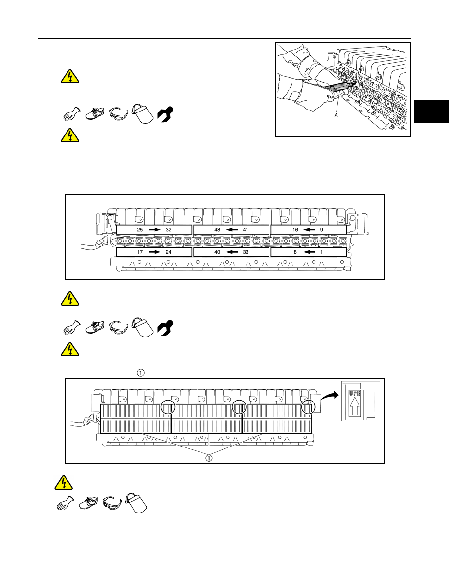
b. Use an insulated torque driver (A) and tighten the voltage detec-

tion terminal mounting screws to the prescribed torque.

DANGER:

 There is the danger of electric shock caused by

contact with the terminals. Be sure to wear insulated pro-

tective gear and use insulated tools.

This work must not be performed by multiple opera-

tors because there is a risk of electric shock if the operators contact one another.

c. Tighten the module terminal mounting bolts in numerical order as shown in the figure.

• When tightening of 1 – 16 is completed, install the left-side bus bar cover.

• When tightening of 17 – 32 is completed, install the right-side bus bar cover.

• When tightening of 33 – 48 is completed, install the center bus bar cover.

DANGER:

 There is the danger of electric shock caused by contact with the terminals. Be sure to wear

insulated protective gear and use insulated tools.

This work must not be performed by multiple operators because there is a risk of electric

shock if the operators contact one another.

d. Install the bus bar cover  .

WARNING:

To prevent electric shock, wear insulated protective gear.

CAUTION:

• Be careful not to install with the top and bottom facing in the wrong directions.

• After installation, check that the mating is not skewed.

JPCIA0135ZZ

JPCIA0136ZZ

JPCIA0137ZZ

EVB-256

< UNIT DISASSEMBLY AND ASSEMBLY >

LI-ION BATTERY

7. Install the harness bracket  ,   and   to the rear module stack.

WARNING:

To prevent electric shock, wear insulated protective gear and use insulated tools.

CAUTION:

• Be sure to reinstall the high voltage harness clips in their original positions. If a clip is damaged,

replace it with a new clip before installing.

• Check the following items after installing battery pack: Refer to 

EVB-256, "Inspection"

.

AIR LEAK INSPECTION
ELECTRIC EQUIPOTENTIAL TEST

Inspection

INFOID:0000000010121190

AIR LEAK INSPECTION

1. Remove the plug and install the adapter (A) of the air leak tester

[SST: KV99111400 ( — )].

WARNING:

To prevent electric shock, wear insulated protective

gear.

2. Install the gauge (A) of the air leak tester [SST: KV99111400

( — )].

WARNING:

To prevent electric shock, wear insulated protective

gear.

CAUTION:

The gauge is a precision instrument. Be careful not to drop

it when handling it.

3. Install the service plug.

DANGER:

 There is the danger of electric shock caused by contact with the terminals. Be sure to wear

insulated protective gear.

JSCIA0635ZZ

JSCIA0645ZZ

JSCIA0646ZZ

LI-ION BATTERY

EVB-257

< UNIT DISASSEMBLY AND ASSEMBLY >

D

E

F

G

H

I

J

K

L

M

A

B

EVB

N

O

P

NOTE:

Because the service plug location is open, install the service plug for sealing the case.

4. Use vinyl tape or similar means (A) for preventing air leakage

from the PTC harness connector.

• Use wide vinyl tape that is capable of covering all of the PTC

harness connector with one strip.

• Apply carefully so that no wrinkles in the tape occur.

WARNING:

To prevent electric shock, wear insulated protective

gear.

5. Use vinyl tape or similar means (A) to prevent air leakage from

the breather.

• Use wide vinyl tape that is capable of covering all of the

breather with one strip.

• Apply carefully so that no wrinkles in the tape occur.

WARNING:

To prevent electric shock, wear insulated protective

gear.

6. Follow the procedure below to check the battery case pressure.

WARNING:

To prevent electric shock, wear insulated protective gear.

a. Open the cock   on the air leak tester.

CAUTION:

Do not operate the pump before opening the cock on the air

leak tester. Doing so may damage the gauge. If the pump is

operated before the cock is opened, first disconnect the air

pump hose to release the pressure.

b. Operate the air pump slowly and apply the specified inspection pressure inside the battery pack. If the

gauge pressure does not rise, or if the gauge reading fluctuates, check for the location of air leakage.

CAUTION:

• Operate the air pump carefully when applying pressure. If pressure is applied suddenly to the

gauge, the gauge may be damaged.

• Do not apply pressure of 2.0 kPa (0.0204 kg/cm

2

) or more to the battery case or air leak tester.

JSCIA0686ZZ

JPCIA0128ZZ

JSCIA0638ZZ

Specified inspection pressure

: 1.6 kPa (0.016 bar, 0.0163 kg/cm

2

, 0.232 psi)

EVB-258

< UNIT DISASSEMBLY AND ASSEMBLY >

LI-ION BATTERY

c.

Close the cock and wait for 1 minute.

d. Check that the air leak tester reading remains at or above the limit value.

e. If the pressure is below the limit value, check for the locations of air leakage.

NOTE:

Check for air leakage from the sound of air escaping when pressure is applied.

ELECTRIC EQUIPOTENTIAL TEST

After assembling the Li-ion battery pack, remove the battery pack upper case ground bolt  , then measure
the resistance between the high-voltage harness connector flange ground bolts   and the ground bolt seat
(location of coating peeling)  .

WARNING:

To prevent electric shock, wear insulated protective gear.

If the result deviates from the standard value, check the following and correct the malfunction location.

• Ground bolt connection condition

• Corrosion on ground bolt mounting surface

• Presence of paint, oil, dirt, or other substance on ground bolt mounting surface

Repair limit

: 1.4 kPa (0.014 bar, 0.0142 kg/cm

2

, 0.203 psi)

Standard

: Less than 0.1

JSCIA0747ZZ


Content   ..  491  492  493  494   ..