Nissan Leaf. Manual - part 491
LI-ION BATTERY
EVB-247
< UNIT DISASSEMBLY AND ASSEMBLY >
D
E
F
G
H
I
J
K
L
M
A
B
EVB
N
O
P
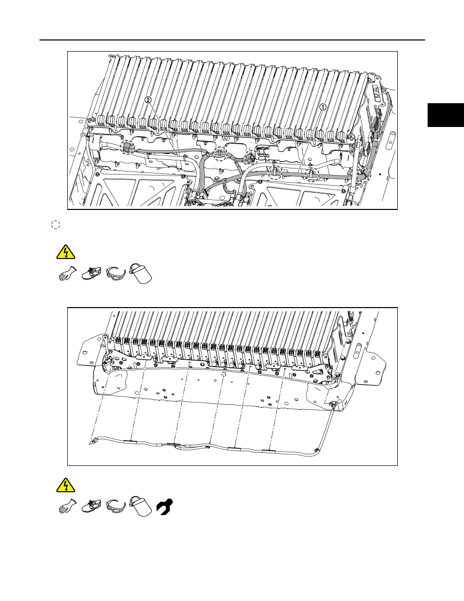
WARNING:
To prevent electric shock, wear insulated protective gear.
6. Install the battery temperature sensor harness (rear).
WARNING:
To prevent electric shock, wear insulated protective gear and use insulated tools.
NOTE:
Install the battery temperature sensor onto module No. MD12.
: Harness clip
JSCIA0769ZZ
JSCIA0647ZZ