Nissan Leaf. Manual - part 470


  Index      Nissan     Nissan Leaf (2011-2014 year) - Service and Repair Manual


Search            


Content   ..  468  469  470  471   ..


Nissan Leaf. Manual - part 470


LI-ION BATTERY INSULATION RESISTANCE LOSS CHECK

EVB-163

< DTC/CIRCUIT DIAGNOSIS >

D

E

F

G

H

I

J

K

L

M

A

B

EVB

N

O

P

LI-ION BATTERY INSULATION RESISTANCE LOSS CHECK

Component Inspection

INFOID:0000000010121165

DANGER:

Since hybrid vehicles and electric vehicles contain a high voltage battery, there is the risk of

electric shock, electric leakage, or similar accidents if the high voltage component and vehicle are

handled incorrectly. Be sure to follow the correct work procedures when performing inspection and

maintenance.

WARNING:

• Be sure to remove the service plug in order to disconnect the high voltage circuits before perform-

ing inspection or maintenance of high voltage system harnesses and parts.

• The removed service plug must always be carried in a pocket of the responsible worker or placed in

the tool box during the procedure to prevent the plug from being connected by mistake.

• Be sure to wear insulating protective equipment consisting of glove, shoes, face shield and glasses

before beginning work on the high voltage system.

• Never allow workers other than the responsible person to touch the vehicle containing high voltage

parts. To keep others from touching the high voltage parts, these parts must be covered with an insu-

lating sheet except when using them.

• Refer to 

EVB-7, "High Voltage Precautions"

.

CAUTION:

Never bring the vehicle into the READY status with the service plug removed unless otherwise

instructed in the Service Manual. A malfunction may occur if this is not observed.

The following diagnosis procedure must be performed when “P0AA6 or P33E1” are detected and Li-ion
battery is judged that its insulation resistance is dropping.

1.

CHECK MAXIMUM CELL VOLTAGE

With CONSULT

1. Power switch ON.

2. Select “DATA MONITOR” of “HV BAT”.

3. Record “MAXIMUM CELL VOLTAGE”.

NOTE:

It is used, when replace a malfunction module.

>> GO TO 2

2.

CHECK INSULATION OF FRONT MODULE STACK LH-1

CAUTION:

Check that high voltage harness and harness shield have no scratches and cracks. If any damage is

found, replace damaged parts.

1. Remove Li-ion battery. Refer to 

EVB-181, "Removal and Installation"

.

2. Remove Li-ion battery controller. Refer to 

EVB-201, "LI-ION BATTERY CONTROLLER : Removal and

Installation"

.

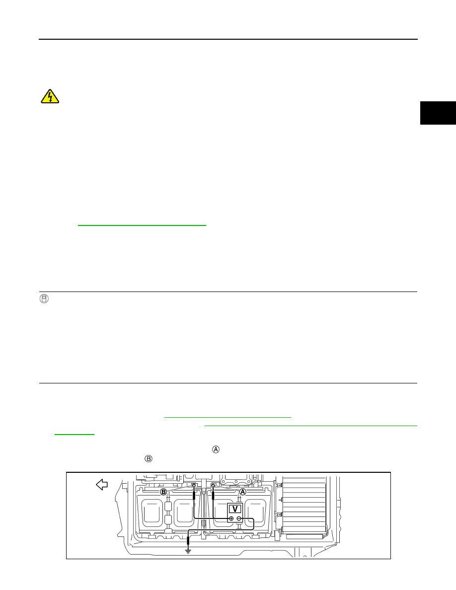
3. Remove bus bar that connects front module stack LH and front module stack RH.
4. Measure voltages between positive terminal   of front module stack LH and battery pack ground, and

between positive terminal   of front module stack LH and battery pack ground.

JSCIA0739ZZ

EVB-164

< DTC/CIRCUIT DIAGNOSIS >

LI-ION BATTERY INSULATION RESISTANCE LOSS CHECK

Is the inspection result normal?

YES

>> GO TO 8.

NO

>> GO TO 3.

3.

CHECK INSULATION OF FRONT MODULE STACK LH-2

1. Disconnect vehicle communication harness connector of front module stack LH.
2. Measure voltages between positive terminal   of front module stack LH and battery pack ground, and

between positive terminal   of front module stack LH and battery pack ground.

Is the inspection result normal?

YES

>> Replace vehicle communication harness of front module stack LH and GO TO 8.

NO

>> GO TO 4.

4.

CHECK INSULATION OF FRONT MODULE STACK LH-3

1. Remove bus bar that connects service plug and front module stack LH.
2. Measure voltages between positive terminal   of front module stack LH and battery pack ground, and

between positive terminal   of front module stack LH and battery pack ground.

: Battery pack front

+

Voltage

Front module stack LH

Terminal

Battery pack ground

Approx. 0 V

: Battery pack front

+

Voltage

Front module stack LH

Terminal

Battery pack ground

Approx. 0 V

JSCIA0739ZZ

: Battery pack front

JSCIA0739ZZ

LI-ION BATTERY INSULATION RESISTANCE LOSS CHECK

EVB-165

< DTC/CIRCUIT DIAGNOSIS >

D

E

F

G

H

I

J

K

L

M

A

B

EVB

N

O

P

Is the inspection result normal?

YES

>> GO TO 5.

NO

>> GO TO 6.

5.

CHECK SERVICE PLUG SWITCH INSULATION RESISTANCE

1. Remove bus bar that connects service plug and front module stack LH from service plug switch bracket.

2. Using insulation resistance tester, measure insulation resistance between service plug switch terminal

and service plug switch bracket.

WARNING:

Unlike the ordinary tester, the insulation resistance tester applies 500 V when measuring. If used

incorrectly, there is the danger of electric shock. If used in the vehicle 12V system, there is the

danger of damage to electronic devices. Read the insulation resistance tester instruction manual

carefully and be sure to work safely.

CAUTION:

Be sure to set the insulation resistance tester to 500 V when performing this test. Using a setting

higher than 500 V can result in damage to the component being inspected.

NOTE:

Check resistance without disassembling service plug switch and service plug switch bracket.

Is the inspection result normal?

YES

>> Replace bus bar that connects service plug and front module stack LH and GO TO 8.

NO

>> Replace service plug switch (Refer to 

EVB-204, "BATTERY JUNCTION BOX AND BATTERY

HARNESS : Exploded View"

.) and GO TO 8.

6.

CHECK MODULE-1

1. Remove front module stack LH. Refer to 

EVB-226, "FRONT MODULE STACK : Removal and Installa-

tion"

.

NOTE:

Do not disassemble module stack.

2. Measure voltages between terminal  /  of all modules in front

module stack LH and module body.

+

Voltage

Front module stack LH

Terminal

Battery pack ground

Approx. 0 V

+

Resistance

Service plug switch terminal

Service plug switch bracket

1000 M

Ω or more

JSCIA0740ZZ

+

Voltage

Module

Terminal

Module body

Approx. 0 V

EVB-166

< DTC/CIRCUIT DIAGNOSIS >

LI-ION BATTERY INSULATION RESISTANCE LOSS CHECK

Is the inspection result normal?

YES

>> GO TO 7.

NO

>> Replace malfunctioning module (Refer to 

EVB-233, "FRONT MODULE STACK : Disassembly

and Assembly"

.) and GO TO 8.

7.

CHECK MODULE-2

Measure insulation resistance between terminal  /  of all modules

in front module stack LH and module body.

WARNING:

Unlike the ordinary tester, the insulation resistance tester

applies 500 V when measuring. If used incorrectly, there is the

danger of electric shock. If used in the vehicle 12V system,

there is the danger of damage to electronic devices. Read the

insulation resistance tester instruction manual carefully and be

sure to work safely.

CAUTION:

Be sure to set the insulation resistance tester to 500 V when

performing this test. Using a setting higher than 500 V can

result in damage to the component being inspected.

Is the inspection result normal?

YES

>> Check insulation resistance of front module stack RH, because front module stack LH is normal.

GO TO 8.

NO

>> Replace malfunctioning module (Refer to 

EVB-233, "FRONT MODULE STACK : Disassembly

and Assembly"

.) and GO TO 8.

8.

CHECK INSULATION OF FRONT MODULE STACK RH-1

1. Measure voltages between positive terminal   of front module stack RH and battery pack ground, and

between positive terminal   of front module stack LH and battery pack ground.

Is the inspection result normal?

YES

>> GO TO 14.

+

resistance

Module

Terminal

Module body

100 M

Ω or more

JSCIA0740ZZ

: Battery pack front

+

Voltage

Front module stack RH

Terminal

Battery pack ground

Approx. 0 V

JSCIA0741ZZ


Content   ..  468  469  470  471   ..