Nissan Leaf. Manual - part 469
P33EE BATTERY HEATER CONTROL SYSTEM
EVB-159
< DTC/CIRCUIT DIAGNOSIS >
D
E
F
G
H
I
J
K
L
M
A
B
EVB
N
O
P
Check resistance of Li-ion battery heater.
Is the inspection result normal?
YES
>> GO TO 5.
NO
>> Replace applicable Li-ion battery heater. Refer to
EVB-215, "LI-ION BATTERY HEATER : Disas-
.
5.
CHECK CONTINUITY OF LI-ION BATTERY HEATER AND BATTERY JUNCTION BOX
1. Disconnect Li-ion battery heater and battery junction box harness connector.
2. Check continuity Li-ion battery heater and battery junction box harness connector.
Is the inspection result normal?
YES
>> GO TO 6
NO
>> Repair harness or connector.
6.
CHECK CONTINUITY OF LI-ION BATTERY HEATER AND HEATER RELAY UNIT
1. Disconnect Li-ion battery heater and heater relay unit harness connector harness connector.
2. Check continuity Li-ion battery heater and heater relay unit harness connector harness connector.
Is the inspection result normal?
YES
>> Replace heater relay unit. Refer to
EVB-221, "LI-ION BATTERY HEATER RELAY UNIT : Disas-
.
NO
>> Repair harness or connector.
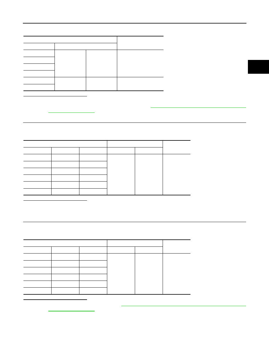
Li-ion battery heater
Resistance
Item
Terminal
LH 1
1
2
Less than 5,269
Ω
LH 2
RH 1
RH 2
RR 1
1
2
Less than 1,265
Ω
RR 2
Li-ion battery heater
Battery junction box
Continuity
Item
Connector
Terminal
Connector
Terminal
LH 1
LB19
2
LB25
15
Existed
LH 2
LB20
2
RH 1
LB23
2
RH 2
LB24
2
RR 1
LB21
2
RR 2
LB22
2
Li-ion battery heater
Heater relay unit
Continuity
Item
Connector
Terminal
Connector
Terminal
LH 1
LB19
1
LB18
11
Existed
LH 2
LB20
1
RH 1
LB23
1
RH 2
LB24
1
RR 1
LB21
1
RR 2
LB22
1