Nissan Leaf. Manual - part 458


  Index      Nissan     Nissan Leaf (2011-2014 year) - Service and Repair Manual


Search            


Content   ..  456  457  458  459   ..


Nissan Leaf. Manual - part 458


P330E-P3319 CELL OVER VOLTAGE

EVB-115

< DTC/CIRCUIT DIAGNOSIS >

D

E

F

G

H

I

J

K

L

M

A

B

EVB

N

O

P

YES

>> Replace Li-ion battery controller. Refer to 

EVB-201, "LI-ION BATTERY CONTROLLER : Removal

and Installation"

.

NO

>> Replace corresponding module. Refer to 

EVB-226, "FRONT MODULE STACK : Removal and

Installation"

.

Component Inspection

INFOID:0000000010121114
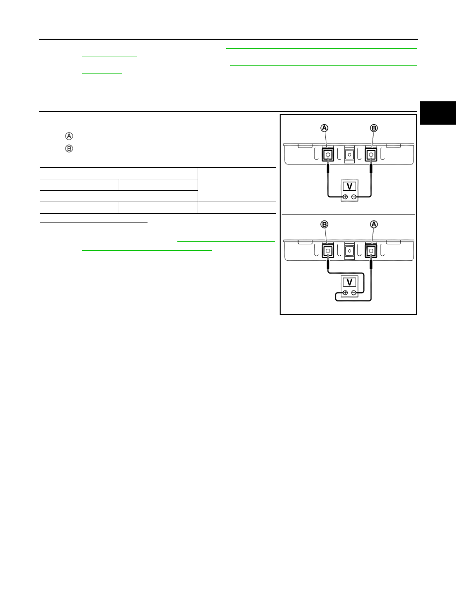
1.

CHECK MODULE VOLTAGE

Check voltage of module.

Is the inspection result normal?

YES

>> INSPECTION END

NO

>> Replace module. Refer to 

EVB-248, "REAR MODULE

STACK : Disassembly and Assembly"

.

: Positive terminal (Red)
: Negative terminal (Black)

Terminals

Voltage

(Approx.)

(+)

(-)

Module

Positive terminal (Red)

Negative terminal (Black)

5.0 - 8.5 V

JSCIA0338ZZ

EVB-116

< DTC/CIRCUIT DIAGNOSIS >

P331A-P3325 CELL OVER VOLTAGE

P331A-P3325 CELL OVER VOLTAGE

DTC Logic

INFOID:0000000010121115

DTC DETECTION LOGIC

DTC CONFIRMATION PROCEDURE

1.

PERFORM DTC CONFIRMATION PROCEDURE

With CONSULT

1. Power switch ON and wait for 10 seconds or more.

2. Select “Self Diagnostic Result” of “HV BAT”.

3. Check DTC.
Is any DTC detected?

YES

>> Refer to 

EVB-119, "Diagnosis Procedure"

.

NO

>> INSPECTION END

Diagnosis Procedure

INFOID:0000000010121116

DANGER:

Since hybrid vehicles and electric vehicles contain a high voltage battery, there is the risk of

electric shock, electric leakage, or similar accidents if the high voltage component and vehicle are

handled incorrectly. Be sure to follow the correct work procedures when performing inspection and

maintenance.

WARNING:

• Be sure to remove the service plug in order to disconnect the high voltage circuits before perform-

ing inspection or maintenance of high voltage system harnesses and parts.

• The removed service plug must always be carried in a pocket of the responsible worker or placed in

the tool box during the procedure to prevent the plug from being connected by mistake.

• Be sure to wear insulating protective equipment consisting of glove, shoes, face shield and glasses

before beginning work on the high voltage system.

• Never allow workers other than the responsible person to touch the vehicle containing high voltage

parts. To keep others from touching the high voltage parts, these parts must be covered with an insu-

lating sheet except when using them.

• Refer to 

EVB-7, "High Voltage Precautions"

.

CAUTION:

Never bring the vehicle into the READY status with the service plug removed unless otherwise

instructed in the Service Manual. A malfunction may occur if this is not observed.

1.

CHECK SELF-DIAGNOSIS RESULTS

With CONSULT

DTC

Trouble diagnosis name

DTC detecting condition

Possible causes

P331A

CELL OVER VOLTAGE MODULE25

When cell voltage exceeds the allowable 
working voltage range.

• Overcharge caused by traction 

motor inverter/VCM malfunc-
tion

• Module
• Li-ion battery controller
• Bus  bar
• Harness or connector

P331B

CELL OVER VOLTAGE MODULE26

P331C

CELL OVER VOLTAGE MODULE27

P331D

CELL OVER VOLTAGE MODULE28

P331E

CELL OVER VOLTAGE MODULE29

P331F

CELL OVER VOLTAGE MODULE30

P3320

CELL OVER VOLTAGE MODULE31

P3321

CELL OVER VOLTAGE MODULE32

P3322

CELL OVER VOLTAGE MODULE33

P3323

CELL OVER VOLTAGE MODULE34

P3324

CELL OVER VOLTAGE MODULE35

P3325

CELL OVER VOLTAGE MODULE36

P331A-P3325 CELL OVER VOLTAGE

EVB-117

< DTC/CIRCUIT DIAGNOSIS >

D

E

F

G

H

I

J

K

L

M

A

B

EVB

N

O

P

1. Perform “All DTC Reading” with CONSULT.

2. Check “Self Diagnostic Result” of systems other than “HV BAT” if any DTC is detected. 
Is any DTC detected?

YES

>> After performing trouble diagnosis of detected DTC, GO TO 2.

NO

>> GO TO 2.

2.

PRECONDITIONING

WARNING:

Disconnect high voltage. Refer to 

GI-33, "How to Disconnect High Voltage"

.

1. Remove Li-ion battery. Refer to 

EVB-181, "Removal and Installation"

.

2. Remove battery pack upper case. Refer to 

EVB-191, "BATTERY PACK UPPER CASE : Removal and

Installation"

.

>> GO TO 3.

3.

CHECK HARNESS BETWEEN MODULE AND LI-ION BATTERY CONTROLLER

With CONSULT

1. Power switch OFF.

2. Identify the malfunctioning module based on detected DTC.

3. Disconnect module harness connector and Li-ion battery controller harness connector.

4. Refer to below table and check the continuity between corresponding module and Li-ion battery controller.

DTC

Module 

No.

Module

Li-ion battery controller

Continuity

Connector

Terminal

Connector

Terminal

P331A

25

LB8

9

LB15

89

Existed

10

110

11

90

P331B

26

LB8

11

LB15

90

Existed

12

111

13

91

P331C

27

LB8

13

LB15

91

Existed

28

112

27

92

P331D

28

LB8

27

LB15

92

Existed

26

113

25

93

P331E

29

LB8

25

LB15

93

Existed

23

114

21

94

P331F

30

LB8

21

LB15

94

Existed

19

115

17

95

P3320

31

LB8

17

LB15

95

Existed

3

116

4

96

P3321

32

LB8

4

LB15

96

Existed

18

117

1

97

EVB-118

< DTC/CIRCUIT DIAGNOSIS >

P331A-P3325 CELL OVER VOLTAGE

Is the inspection result normal?

YES

>> GO TO 4.

NO

>> Repair harness or connector.

4.

CHECK MODULE VOLTAGE

Check voltage of corresponding module. Refer to 

EVB-118, "Component Inspection"

.

Is the inspection result normal?

YES

>> Replace Li-ion battery controller. Refer to 

EVB-201, "LI-ION BATTERY CONTROLLER : Removal

and Installation"

.

NO

>> Replace corresponding module. Refer to 

EVB-233, "FRONT MODULE STACK : Disassembly and

Assembly"

.

Component Inspection

INFOID:0000000010121117

1.

CHECK MODULE VOLTAGE

Check voltage of module.

Is the inspection result normal?

YES

>> INSPECTION END

NO

>> Replace module. Refer to 

EVB-233, "FRONT MODULE

STACK : Disassembly and Assembly"

.

P3322

33

LB8

1

LB15

97

Existed

2

118

20

99

P3323

34

LB8

20

LB15

99

Existed

6

119

8

100

P3324

35

LB8

8

LB15

100

Existed

22

120

5

101

P3325

36

LB8

5

LB15

101

Existed

7

121

24

102

DTC

Module 

No.

Module

Li-ion battery controller

Continuity

Connector

Terminal

Connector

Terminal

: Positive terminal (Red)
: Negative terminal (Black)

Terminals

Voltage

(Approx.)

(+)

(-)

Module

Positive terminal (Red)

Negative terminal (Black)

5.0 - 8.5 V

JSCIA0338ZZ


Content   ..  456  457  458  459   ..