Nissan Leaf. Manual - part 352


  Index      Nissan     Nissan Leaf (2011-2014 year) - Service and Repair Manual


Search            


Content   ..  350  351  352  353   ..


Nissan Leaf. Manual - part 352


BRM-32

< REMOVAL AND INSTALLATION >

BODY CONSTRUCTION

Rear Fender Hemming Process

INFOID:0000000010121696

1. A wheel arch is to be installed and hemmed over the left and right outer wheel houses.

2. In order to hem the wheel arch, it is necessary to repair any damaged or defaced parts around outer

wheel house.

CAUTION:

Ensure that the area that is to be glued around the outer wheelhouse is undamaged or defaced.

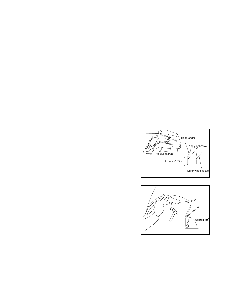
PROCEDURE OF THE HEMMING PROCESS

• Peel off old bonding material on the surface of the outer wheel-

house and clean thoroughly.

• Peel off a primer coat in the specified area where new adhesive is

to be applied on rear fender (the replacing part).

• Apply new adhesive to both specified areas of the outer wheel-

house and rear fender.

• Attach rear fender to the body of the car, and weld the required

part except the hemming part.

• Bend the welded part starting from the center of the wheel arch

gradually with a hammer and a dolly. (Also hem the end of the

flange.)

• Hemming with a hammer is conducted to an approximate angle of

80 degrees.

10. Lower dash

11. Lower front pillar hinge brace

12. Lower hinge plate

13. Inner front sill reinforcement

14. Inner sill

15. Front side member extension center

16. Front side member closing plate

17. Front outrigger

18. Front floor front

19. Lower front pillar reinforcement

20. Outer sill reinforcement

21. Outer sill brace

22. Front side member extension rear

23. Floor member extension

24. Center sill reinforcement

25. Roof

26. Center roof reinforcement

27. Roof member reinforcement

28. Inner center pillar

29. Center pillar seat belt anchor

30. Center pillar reinforcement

31. Center pillar hinge brace

32. Outer side roof rail

33. Front floor side

34. Rear side member closing plate

35. Rear side member reinforcement

36. Rear side member

37. Inner sill extension

38. Inner rear sill reinforcement

39. Outer rear wheelhouse extension

40. Inner rear wheelhouse

41. Outer rear wheelhouse

42. Rear fender extension

43. Back door stay bracket

44. Inner rear pillar

45. Rear roof rail brace

46. Inner rear pillar reinforcement

47. Rear pillar seat belt anchor

<Adhesive> 3M™ Automix™ Panel Bonding Adhe-

sive 08115 or equivalent

JSKIA0136GB

SIIA2245E

BODY CONSTRUCTION

BRM-33

< REMOVAL AND INSTALLATION >

C

D

E

F

G

H

I

J

L

M

A

B

BRM

N

O

P

• Starting from the center, hem the wheel arch gradually, using slight

back and forth motion with a hemming tool.

• Seal up the area around the hemmed end of the flange.

SIIA2246E

JSKIA0137GB

BRM-34

< REMOVAL AND INSTALLATION >

REPLACEMENT OPERATIONS

REPLACEMENT OPERATIONS

Description

INFOID:0000000010121697

• This section is prepared for technicians who have attained a high level of skill and experience in repairing

collision-damaged vehicles and also use modern service tools and equipment. Persons unfamiliar with body

repair techniques should not attempt to repair collision-damaged vehicles by using this section.

• Technicians are also encouraged to read the Body Repair Manual (Fundamentals) in order to ensure that the

original functions and quality of the vehicle are maintained. The Body Repair Manual (Fundamentals) con-

tains additional information, including cautions and warnings, that are not including in this manual. Techni-

cians should refer to both manuals to ensure proper repair.

• Please note that this information is prepared for worldwide usage, and as such, certain procedures might not

apply in some regions or countries.

The symbols used in this section for welding operations are shown below.

Symbol marks

Description

2-spot welds

3-spot welds

MIG plug weld

For 3 panels plug weld method

MIG seam weld / Point weld

JSKIA0049ZZ

JSKIA0053ZZ

JSKIA0050ZZ

JSKIA0051ZZ

JSKIA0054ZZ

JSKIA0055ZZ

JSKIA0052ZZ

JSKIA0056ZZ

REPLACEMENT OPERATIONS

BRM-35

< REMOVAL AND INSTALLATION >

C

D

E

F

G

H

I

J

L

M

A

B

BRM

N

O

P

• Front pillar butt joint can be determined anywhere within shaded

area (A) as shown in the figure. The best location for the butt joint

is within the (B) location due to the construction of the vehicle.

• Determine cutting position and record distance from the locating

indent (B) Use this distance when cutting the service part. Cut

outer front pillar (A) over 60 mm (2.36 in) above the inner front pil-

lar cut position.

• Prepare a cutting jig to make outer pillar easier to cut. Also, this will

permit the service part to be accurately cut at the joint position.

• An example of cutting operation using a cutting jig is as per the fol-

lowing.

1. Mark cutting lines cut position of outer pillar (A) and the inner pil-

lar.

2. Align cutting line with notch on jig. Clamp jig to pillar.

3. Cut outer pillar along groove of jig (at position A).

4. Remove jig and cut remaining portions.

5. Cut inner pillar in same manner.

PIIA0150E

JSKIA0104GB

JSKIA0105GB

PIIA0153E


Content   ..  350  351  352  353   ..