Nissan Leaf. Manual - part 324


  Index      Nissan     Nissan Leaf (2011-2014 year) - Service and Repair Manual


Search            


Content   ..  322  323  324  325   ..


Nissan Leaf. Manual - part 324


BRC-86

< DTC/CIRCUIT DIAGNOSIS >

[WITH VDC]

C1113, C1145, C1146 YAW RATE/SIDE/DECEL G SENSOR

Is the inspection result normal?

YES

>> GO TO 4.

NO

>> Repair or replace error-detected parts, securely lock the connector, and GO TO 3.

3.

PERFORM SELF DIAGNOSTIC

With CONSULT

1. Turn the power switch OFF 

→ ON.

CAUTION:

• Be sure to wait of 10 seconds after turning power switch OFF or ON.

• Set the vehicle to READY.

2. Repeat step 1 two or more times.

3. Perform “Self Diagnostic Result” of “ABS”.
Is DTC“C1113”, “C1145” or “C1146” detected?

YES

>> GO TO 4.

NO

>> Inspection End.

4.

CHECK YAW RATE/SIDE/DECEL G SENSOR POWER SUPPLY CIRCUIT

1. Turn power switch OFF.

2. Disconnect ABS actuator and electric unit (control unit) harness connector.

3. Disconnect yaw rate/side/decel G sensor harness connector.

4. Check the continuity between yaw rate/side/decel G sensor harness connector and ABS actuator and

electric unit (control unit) harness connector.

Is the inspection result normal?

YES

>> GO TO 5.

NO

>> Repair or replace error-detected parts.

5.

CHECK YAW RATE/SIDE/DECEL G SENSOR GROUND CIRCUIT

Check the continuity between yaw rate/side/decel G sensor harness connector and ABS actuator and electric

unit (control unit) harness connector.

Is the inspection result normal?

YES

>> GO TO 6.

NO

>> Repair or replace error-detected parts.

6.

CHECK YAW RATE/SIDE/DECEL G SENSOR SIGNAL CIRCUIT

Check the continuity between yaw rate/side/decel G sensor harness connector and ABS actuator and electric

unit (control unit) harness connector.

Is the inspection result normal?

YES

>> GO TO 7.

NO

>> Repair or replace error-detected parts.

7.

CHECK YAW RATE/SIDE/DECEL G SENSOR CIRCUIT

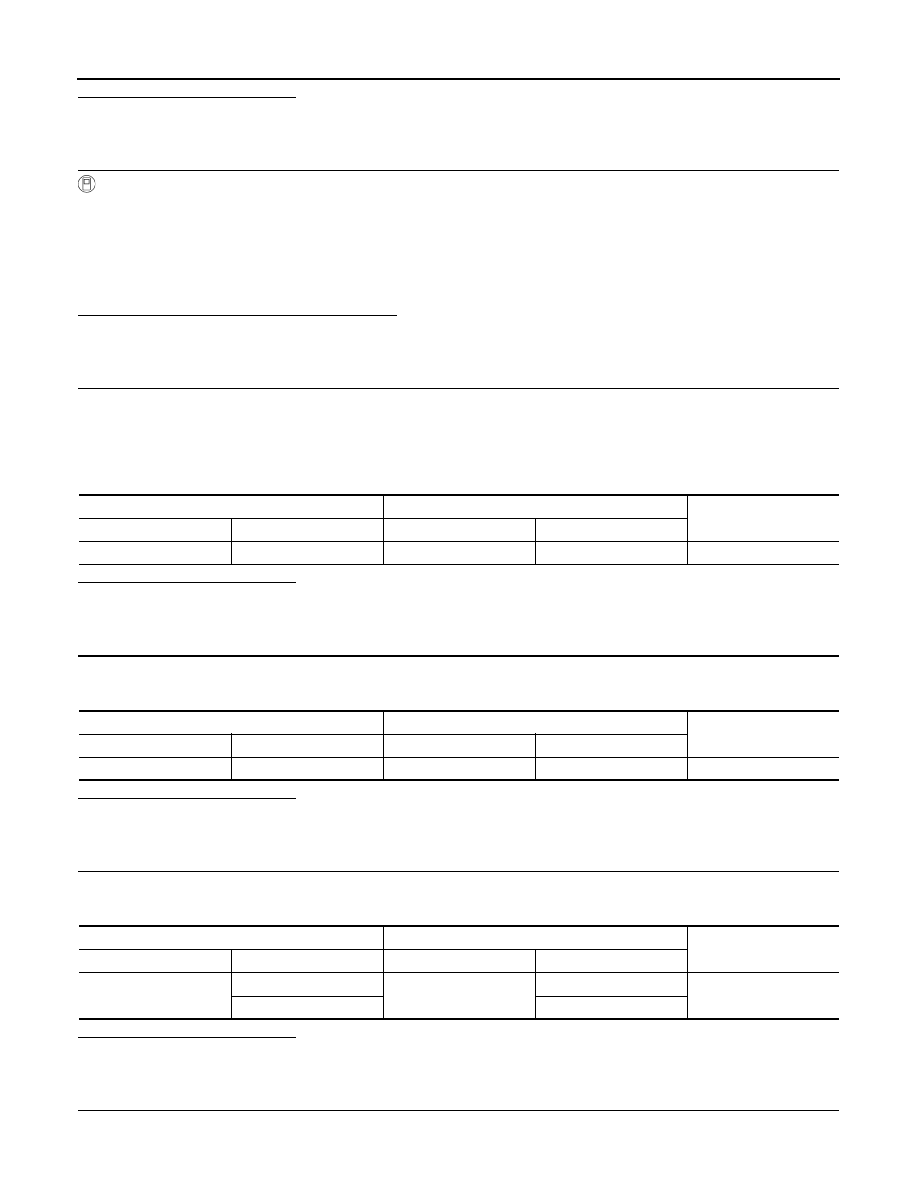
Check the continuity between each terminals of yaw rate/side/decel G sensor harness connector.

ABS actuator and electric unit (control unit)

Yaw rate/side/decel G sensor

Continuity

Connector

Terminal

Connector

Terminal

E35

13

B38

4

Yes

ABS actuator and electric unit (control unit)

Yaw rate/side/decel G sensor

Continuity

Connector

Terminal

Connector

Terminal

E35

28

B38

2

Yes

ABS actuator and electric unit (control unit)

Yaw rate/side/decel G sensor

Continuity

Connector

Terminal

Connector

Terminal

E35

14

B38

5

Yes

29

6

C1113, C1145, C1146 YAW RATE/SIDE/DECEL G SENSOR

BRC-87

< DTC/CIRCUIT DIAGNOSIS >

[WITH VDC]

C

D

E

G

H

I

J

K

L

M

A

B

BRC

N

O

P

Is the inspection result normal?

YES

>> GO TO 8.

NO

>> Repair or replace error-detected parts.

8.

CHECK YAW RATE/SIDE/DECEL G SENSOR (1)

With CONSULT

1. Connect yaw rate/side/decel G sensor harness connector.

2. Connect ABS actuator and electric unit (control unit) harness connector.

3. Turn the power switch ON.

CAUTION:

Never set the vehicle to READY.

4. Select “ABS”, “Data Monitor” and “DECEL G-SEN” in order.

5. Move yaw rate/side/decel G sensor as shown in the figure to

check the output of before and after moving the sensor.

Is the inspection result normal?

YES

>> GO TO 9.

NO

>> Replace yaw rate/side/decel G sensor. Refer to 

BRC-

164, "Removal and Installation"

.

9.

CHECK YAW RATE/SIDE/DECEL G SENSOR (2)

1. Turn the power switch OFF.

2. Connect following terminals between yaw rate/side/decel G sensor and harness connector (test harness).

3. Turn the power switch ON.

CAUTION:

Never set the vehicle to READY.

4. Check the voltage between yaw rate/side/decel G sensor harness connector terminals.

CAUTION:

Never short out the terminals while measuring voltages.

Yaw rate/side/decel G sensor

Continuity

Connector

Terminal

B38

− 4

No

− 5

− 6

− 5

− 6

− 6

Condition

DATA MONITOR

Horizontal

Approx. 0 G

Vertical

Approx. +1 G

JSFIA0098ZZ

Yaw rate/side/decel G sensor

Harness connector

Connector

Terminal

2

B38

2

4

4

5

5

6

6

BRC-88

< DTC/CIRCUIT DIAGNOSIS >

[WITH VDC]

C1113, C1145, C1146 YAW RATE/SIDE/DECEL G SENSOR

Is the inspection result normal?

YES

>> Replace ABS actuator end electric unit (control unit). Refer to 

BRC-162, "Removal and Installa-

tion"

.

NO

>> Replace yaw rate/side/decel G sensor. Refer to 

BRC-164, "Removal and Installation"

.

Yaw rate/side/decel G sensor

Voltage

(Approx.)

connector

Terminal

B38

5 – 2

2.5 – 4.5 V

6 – 2

0.5 – 2.5 V

C1115 WHEEL SENSOR

BRC-89

< DTC/CIRCUIT DIAGNOSIS >

[WITH VDC]

C

D

E

G

H

I

J

K

L

M

A

B

BRC

N

O

P

C1115 WHEEL SENSOR

DTC Logic

INFOID:0000000010120066

DTC DETECTION LOGIC

DTC CONFIRMATION PROCEDURE

1.

PRECONDITIONING

If “DTC CONFIRMATION PROCEDURE” has been previously conducted, always turn power switch OFF and

wait at least 10 seconds before conducting the next test.

>> GO TO 2.

2.

CHECK DTC DETECTION

With CONSULT

1. Set the vehicle to READY.

2. Drive the vehicle at approx. 30 km/h (19 MPH) or more for approx. 1 minute.

3. Stop the vehicle.

4. Turn the power switch OFF 

→ ON.

CAUTION:

• Be sure to wait of 10 seconds after turning power switch OFF or ON.

• Set the vehicle to READY.

5. Repeat step 4 two or more times.

6. Perform “Self Diagnostic Result” of “ABS”.
Is DTC “C1115” detected?

YES

>> Proceed to 

BRC-89, "Diagnosis Procedure"

.

NO

>> Inspection End.

Diagnosis Procedure

INFOID:0000000010120067

Regarding Wiring Diagram information. Refer to 

BRC-58, "Wiring Diagram"

.

CAUTION:

Never check the between wheel sensor harness connector terminals.

1.

CHECK ABS ACTUATOR AND ELECTRIC UNIT (CONTROL UNIT) POWER SUPPLY SYSTEM

Check the ABS actuator and electric unit (control unit) power supply system. Refer to 

BRC-137, "Diagnosis

Procedure"

.

Is the inspection result normal?

YES

>> GO TO 2.

NO

>> Repair or replace error-detected parts.

2.

CHECK TIRE

1. Turn the power switch OFF.

2. Check the tire air pressure, wear and size. Refer to 

WT-51, "Tire Air Pressure"

.

Is the inspection result normal?

YES

>> GO TO 5.

NO

>> Adjust air pressure or replace tire and GO TO 3.

DTC

Display Item

Malfunction detected condition

Possible causes

C1115

ABS SENSOR [ABNORMAL 
SIGNAL]

When difference in wheel speed between any wheel 
and others is detected the vehicle is driven, because 
of installation of other tires than specified.

• Harness or connector
• Wheel sensor
• Sensor rotor
• ABS actuator and electric unit 

(control unit)

• Tire


Content   ..  322  323  324  325   ..