Nissan Leaf. Manual - part 305
BRC-10
< SYSTEM DESCRIPTION >
[WITH VDC]
COMPONENT PARTS
SYSTEM DESCRIPTION
COMPONENT PARTS
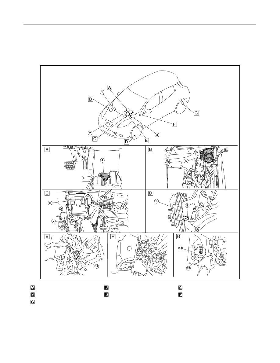
Component Parts Location
INFOID:0000000010120019
ALFIA0456ZZ
Console body assembly
Inside motor room (right)
Inside motor room (left)
Steering knuckle
Brake pedal
Back of spiral cable assembly
Rear wheel hub assembly