Nissan Leaf. Manual - part 301


  Index      Nissan     Nissan Leaf (2011-2014 year) - Service and Repair Manual


Search            


Content   ..  299  300  301  302   ..


Nissan Leaf. Manual - part 301


REAR DISC BRAKE

BR-525

< REMOVAL AND INSTALLATION >

C

D

E

G

H

I

J

K

L

M

A

B

BR

N

O

P

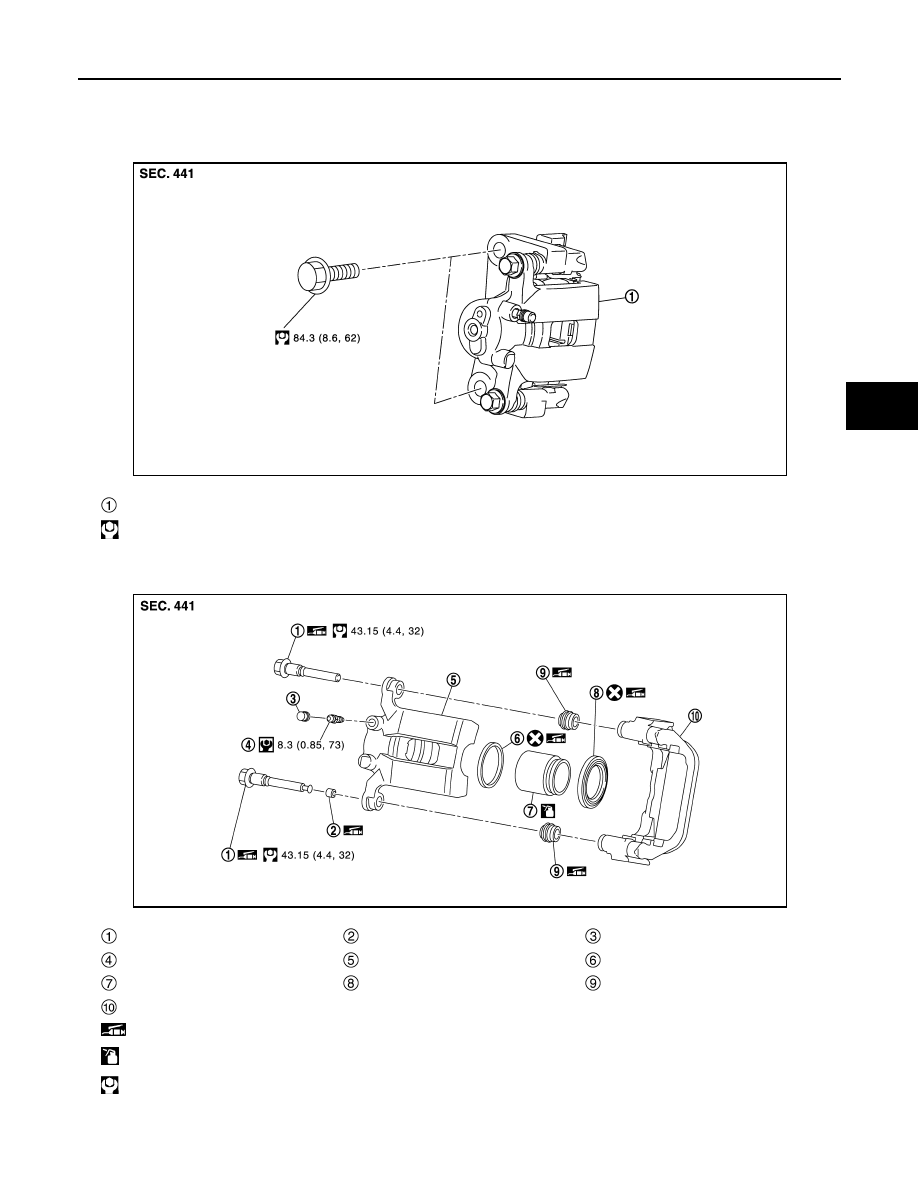
BRAKE CALIPER ASSEMBLY : Exploded View

INFOID:0000000010123154

REMOVAL

DISASSEMBLY

Brake caliper assembly

: N·m (kg-m, ft-lb)

JPFIA0677GB

Sliding pin bolt

Bushing

Cap

Bleeder valve

Cylinder body

Piston seal

Piston

Piston boot

Sliding pin boot

Torque member

: Apply rubber grease.

: Apply brake fluid.

: N·m (kg-m, ft-lb)

JSFIA0494GB

BR-526

< REMOVAL AND INSTALLATION >

REAR DISC BRAKE

BRAKE CALIPER ASSEMBLY : Removal and Installation

INFOID:0000000010123155

REMOVAL

WARNING:

Since dust covering the front and rear brakes has an affect on human body, the dust must be removed

with a dust collector. Do not splatter the dust with an air blow gun.

CAUTION:

• Do not spill or splash brake fluid on painted surfaces. Brake fluid may seriously damage paint. Wipe

it out immediately and wash with water if it gets on a protect surface. For brake component parts, do

not wash them with water.

• Do not depress brake pedal. While removing the brake hose. If this is not complied with, brake fluid

may splash.

• Do not drop removed parts.

• Do not spill or splash brake fluid on the disc rotor.

• To prevent damage to the parts, if the brake fluid or grease adheres to the disc rotor, quickly wipe it

off.

NOTE:

When removing components such as hoses, tubes/lines, etc., cap or plug openings to prevent fluid from spill-

ing.
1. Remove wheel and tire using power tool. Refer to 

WT-45, "Removal and Installation"

.

2. Fix the disc rotor using wheel nuts.
3. Drain brake fluid. Refer to 

BR-493, "Draining"

.

4. Separate brake hose from caliper assembly. Refer to 

BR-507, "REAR : Removal and Installation"

.

5. Remove torque member bolts, and remove brake caliper

assembly.

CAUTION:

Do not drop brake pad and caliper assembly.

6. When removing disc rotor. Refer to 

RAX-7, "Removal and Instal-

lation"

.

INSTALLATION

WARNING:

Since dust covering the front and rear brakes has an affect on human body, the dust must be removed

with a dust collector. Do not splatter the dust with an air blow gun.

CAUTION:

• Do not spill or splash brake fluid on painted surfaces. Brake fluid may seriously damage paint. Wipe

it out immediately and wash with water if it gets on a protect surface. For brake component parts, do

not wash them with water.

• Do not depress brake pedal. While removing the brake hose. If this is not complied with, brake fluid

may splash.

• Do not spill or splash brake fluid on the disc rotor.

• To prevent damage to the parts, if the brake fluid or grease adheres to the disc rotor, quickly wipe it

off.

1. Install disc rotor. Refer to 

RAX-7, "Removal and Installation"

.

: N·m (kg-m, in-lb)

: Always replace after every disassembly.

JSFIA0495ZZ

REAR DISC BRAKE

BR-527

< REMOVAL AND INSTALLATION >

C

D

E

G

H

I

J

K

L

M

A

B

BR

N

O

P

2. Install the brake caliper assembly to the axle housing and

tighten the torque member bolts to the specified torque.

CAUTION:

Do not spill or splash any grease and moisture on the brake

caliper assembly mounting face, threads, bolts and wash-

ers. Wipe out any grease and moisture.

3. Install brake hose. Refer to 

BR-507, "REAR : Removal and

Installation"

.

4. Perform the air bleeding. Refer to 

BR-494, "Bleeding Brake Sys-

tem"

.

5. Check a drag of rear disc brake. If any drag is found, refer to

BR-524, "BRAKE PAD : Inspection"

.

6. Install wheel and tire. Refer to 

WT-45, "Removal and Installation"

.

7. Perform inspection after installation. Refer to 

BR-529, "BRAKE CALIPER ASSEMBLY : Inspection"

.

BRAKE CALIPER ASSEMBLY : Disassembly and Assembly

INFOID:0000000010123156

DISASSEMBLY

NOTE:

Do not remove the torque member, brake pad and pad retainers when disassembling and assembling the cyl-

inder body.
1. Remove the sliding pin bolt, and remove the cylinder body from the torque member. Refer to 

BR-522,

"BRAKE PAD : Removal and Installation"

.

CAUTION:

To prevent damage to the parts, fix the brake pad at suitable tape so that the brake pad will not

drop.

2. Remove sliding pin boots from torque member.
3. Remove bushing   from sliding pin bolt  .

4. Place a wooden block as shown, and blow air from union bolt

mounting hole to remove pistons and piston boots.

WARNING:

Do not get fingers caught in the pistons.

JSFIA0495ZZ

JSFIA0496ZZ

MAA0272D

BR-528

< REMOVAL AND INSTALLATION >

REAR DISC BRAKE

5. Remove piston seal from cylinder body using seal pick tool.

CAUTION:

To prevent damage to the parts, be careful not to damage a

cylinder inner wall.

6. Remove bleeder valve and cap.
7. Perform inspection after disassembly. Refer to 

BR-529, "BRAKE

CALIPER ASSEMBLY : Inspection"

.

ASSEMBLY

1. Install bleeder valve and cap.
2. Apply rubber grease to piston seals  , and install them to cylin-

der body.

CAUTION:

Do not reuse piston seals.

3. Apply rubber grease to piston boots  . Cover the piston   end

with piston boot, and then install cylinder side lip on piston boot

securely into a groove on cylinder body.

CAUTION:

Do not reuse piston boots.

4. Apply new brake fluid to pistons  . Push piston into cylinder

body by hand and push piston boot   piston-side lip into the pis-

ton groove.

CAUTION:

To prevent damage to the parts, press the pistons evenly

and vary the pressing point to prevent cylinder inner wall

from being rubbed.

JPFIA0738ZZ

JPFIA0039ZZ

JPFIA0739ZZ

JPFIA0034ZZ


Content   ..  299  300  301  302   ..