Content .. 1274 1275 1276 1277 ..
Nissan Leaf. Manual - part 1276
WCS
COMBINATION METER
WCS-31
< ECU DIAGNOSIS INFORMATION >
C
D
E
F
G
H
I
J
K
L
M
B
A
O
P
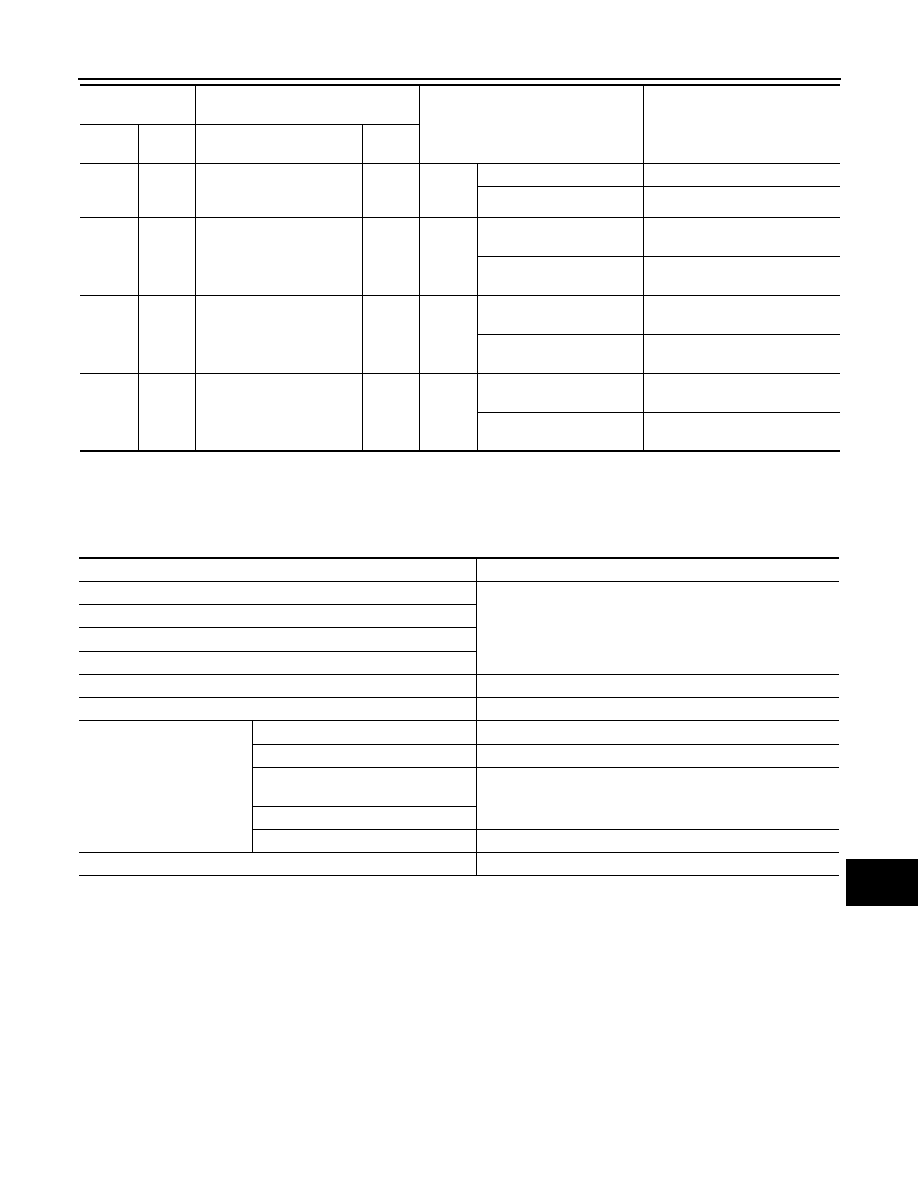
Fail-Safe
INFOID:0000000010505314
FAIL-SAFE
• The combination meter activates the fail-safe control if CAN communication with each unit is malfunctioning.
34
(L)
Ground
Plug in indicator lamp sig-
nal
Input
Power
switch
ON
Plug in indicator lamp ON
0 V
Plug in indicator lamp OFF
Battery voltage
38
(V)
Ground
LED headlamp (RH) warn-
ing signal
Input
Power
switch
ON
Front combination lamp RH
malfunction
Battery voltage
Front combination lamp RH
normal
0 V
39
(LG)
Ground
LED headlamp (LH) warn-
ing signal
Input
Power
switch
ON
Front combination lamp LH
malfunction
Battery voltage
Front combination lamp LH
normal
0 V
40
(W)
Ground
Seat belt buckle switch sig-
nal (driver side)
Input
Power
switch
ON
When driver seat belt is fas-
tened
Battery voltage
When driver seat belt is un-
fastened
0 V
Terminal No.
(Wire color)
Description
Condition
Value
(Approx.)
+
–
Signal name
Input/
Output
Function
Specifications
Power meter
The display turns OFF by suspending communication.
Li-ion battery temperature gauge
Li-ion battery capacity level gauge
Li-ion battery available charge gauge
Driving range display
The display turns “– – –” by suspending communication.
Illumination control
When suspending communication, changes to nighttime mode.
Information display
Odo/trip meter
An indicated value is maintained at communications blackout.
Shift indicator
The display turns OFF by suspending communication.
Li-ion low battery charge warning dis-
play
The display turns ON by suspending communication.
Electric shift warning display
Other than the above
The display turns OFF by suspending communication.
Buzzer
The buzzer turns OFF by suspending communication.