Content .. 1269 1270 1271 1272 ..
Nissan Leaf. Manual - part 1271
WCS
SYSTEM
WCS-11
< SYSTEM DESCRIPTION >
C
D
E
F
G
H
I
J
K
L
M
B
A
O
P
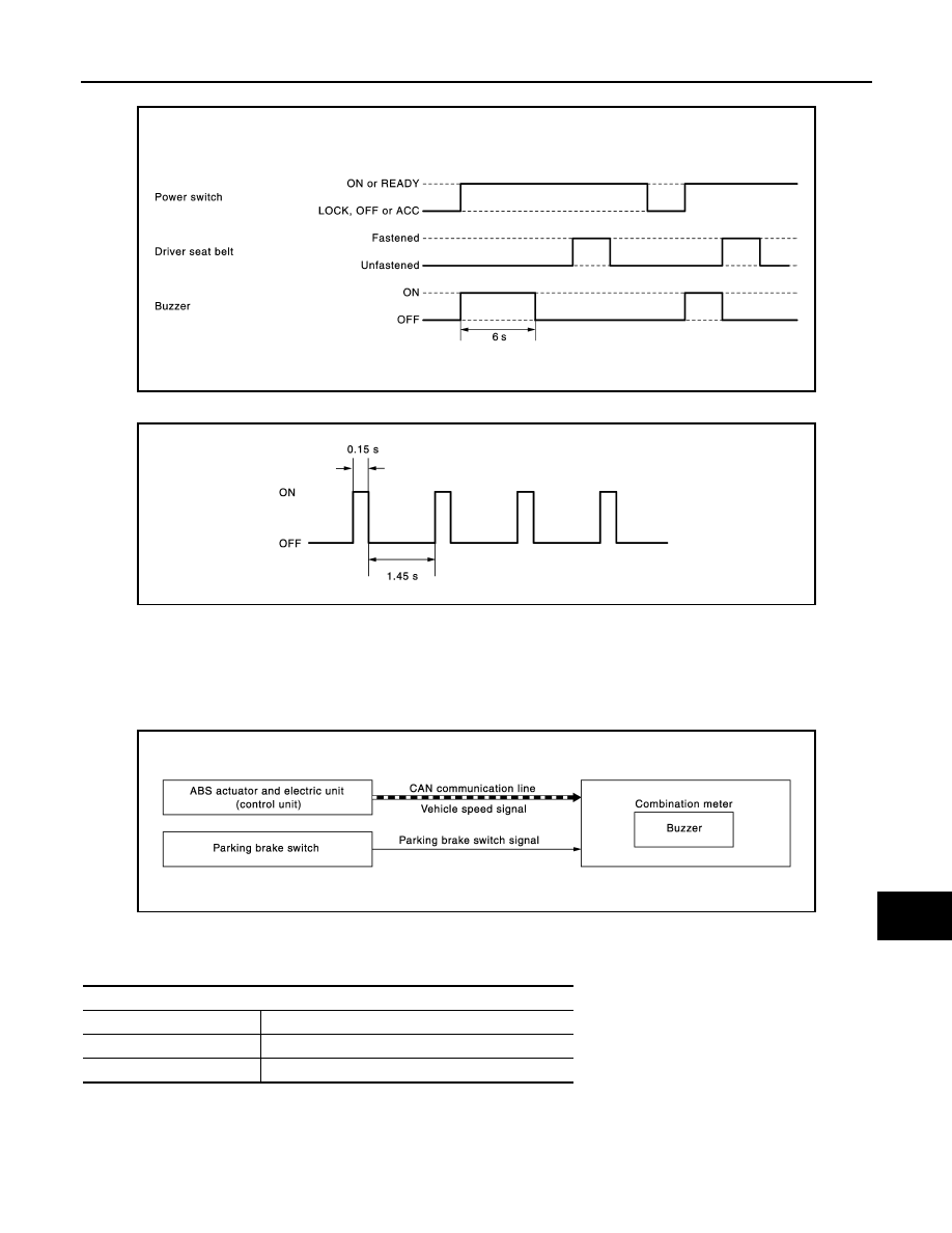
TIMING CHART
SOUND SPECIFICATION
PARKING BRAKE RELEASE WARNING CHIME
PARKING BRAKE RELEASE WARNING CHIME : Parking Brake Release Warning
Chime
INFOID:0000000010121626
SYSTEM DIAGRAM
WARNING OPERATION CONDITIONS
If all of the following conditions are fulfilled:
WARNING CANCEL CONDITIONS
Warning is canceled if any of the following conditions are fulfilled:
JSNIA4176GB
JSNIA3111GB
JSNIA2422GB
Operation conditions
Power switch
ON
Parking brake
During the operation (parking brake switch ON)
Vehicle speed
Approximately 4.3 MPH (7 km/h) or more