Content .. 1255 1256 1257 1258 ..
Nissan Leaf. Manual - part 1257
VSP-48
< DTC/CIRCUIT DIAGNOSIS >
APPROACHING VEHICLE SOUND FOR PEDESTRIANS (VSP) SPEAKER SIG-
NAL CIRCUIT
APPROACHING VEHICLE SOUND FOR PEDESTRIANS (VSP) SPEAKER
SIGNAL CIRCUIT
Description
INFOID:0000000010121588
The VSP control unit outputs the VSP speaker signal to the VSP speaker.
Component Function Check
INFOID:0000000010121589
1.
CHECK VSP SPEAKER OPERATION
1. Connect the CONSULT.
2. Turn power switch ON.
3. Select the “ACTIVE TEST” item “VSP SPEAKER” of “VSP”.
4. Activate “VSP SPEAKER” and check that VSP speaker operates.
Is the inspection result normal?
YES
>> INSPECTION END
NO
>> Refer to
.
Diagnosis Procedure
INFOID:0000000010121590
1.
CHECK VSP SPEAKER SIGNAL CIRCUIT
1. Turn power switch OFF.
2. Disconnect VSP control unit and VSP speaker connector.
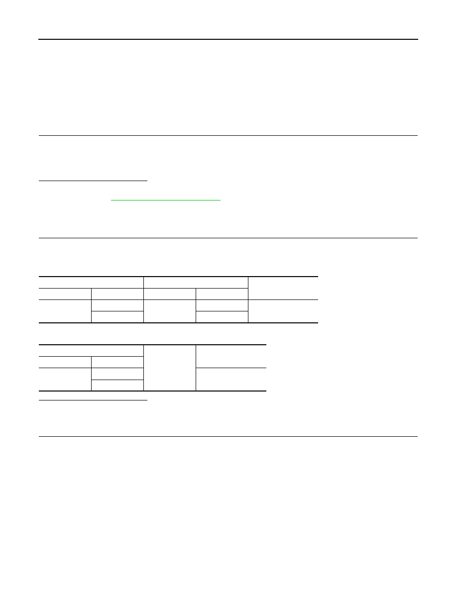
3. Check continuity between VSP control unit harness connector and VSP speaker harness connector.
4. Check continuity between VSP control unit harness connector and ground.
Is the inspection result normal?
YES
>> GO TO 2.
NO
>> Repair harness or connector.
2.
CHECK VSP SPEAKER OUTPUT SIGNAL
1. Connect VSP control unit and VSP speaker connector.
2. Connect the CONSULT.
3. Turn power switch ON.
4. Select the “ACTIVE TEST” for the “VSP” and perform the “VSP SPEAKER”.
5. Check signal between VSP control unit harness connector.
VSP control unit
VSP speaker
Continuity
Connector
Terminal
Connector
Terminal
M47
7
E42
2
Existed
8
1
VSP control unit
Ground
Continuity
Connector
Terminal
M47
7
Not existed
8