Nissan Leaf. Manual - part 1250


  Index      Nissan     Nissan Leaf (2011-2014 year) - Service and Repair Manual


Search            


Content   ..  1248  1249  1250  1251   ..


Nissan Leaf. Manual - part 1250


VSP-20

< SYSTEM DESCRIPTION >

SYSTEM

REVERSE SOUND

The reverse sound is a function that operates when the selector lever is in the “R” position.

Operation Description

• The VCM transmits the following signals to the VSP control unit via CAN communication. 

- Shift position signal

- READY to drive indicator lamp request signal

• The VSP control unit judges that the reverse sound is necessary according to the signals received from the

VCM. 

• When the VSP control unit judges that operation of the reverse sound is necessary, it transmits the VSP

speaker signal to the VSP speaker. 

Operation Condition

The reverse sound operates when all of the following conditions are met. 

Operation Stop Condition

The reverse sound operation stops when any of the following conditions is met.

Signal Path

• The VSP control unit judges that the reverse sound is necessary according to the following signals, and

operates the reverse sound. 

• When the VSP control unit judges that the reverse sound is necessary, it transmits the following signal. 
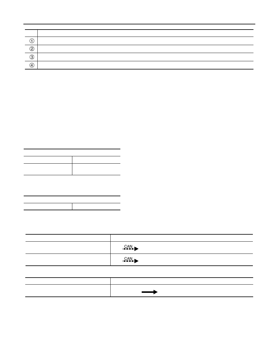
No.

Description

When accelerating, the driving sound operates up to approximately 30 km/h (19 MPH). 

When the speed is more than 30 km/h (19 MPH), the driving sound stops. 

When decelerating, the driving sound operates when the speed is approximately 25 km/h (16 MPH) or less. 

The driving sound stops when the vehicle is stopped (fades out and stops).

Operation condition

Selector lever

“R” position

READY to drive indicator 
lamp

ON

Operation stop condition

Selector lever

Other than “R” position

Signal name

Signal path

READY to drive indicator lamp request signal

VCM 

 VSP control unit

Shift position signal

VCM 

 VSP control unit

Signal name

Signal path

VSP speaker signal

VSP control unit 

 VSP speaker

SYSTEM

VSP-21

< SYSTEM DESCRIPTION >

C

D

E

F

G

H

I

J

K

M

A

B

VSP

N

O

P

Timing Chart

 VSP SYSTEM OPERATION STOP AND RESUME FUNCTION

• The VSP system can be set to stop operating or to resume operating with the VSP OFF switch. 

• The VSP system starts operating when the power switch is turned from OFF to READY. 

• While operation of the VSP system is stopped, the VSP OFF indicator turns ON. 

Operation Description

• The VSP OFF switch transmits the VSP OFF switch signal to the VSP control unit. 

• The VSP control unit judges VSP system operation stop or operation resume according to the VSP OFF

switch signal.

• The VSP control unit transmits the VSP OFF indicator signal to the VSP OFF switch.

Stopping VSP System Operation

• Press the VSP OFF switch.

• Check that the VSP OFF indicator turns ON.

Cancelling VSP System Operation Stop

• Press the VSP OFF switch.

• Check that the VSP OFF indicator turns OFF.

NOTE:

Even if VSP system operation is stopped when the power switch is turned OFF, the VSP system starts to oper-

ate when the power switch is next turned from OFF to READY.

Signal Path

• The VSP control unit judges VSP system operation stop and operation resume according to the following

signal. 

• The VSP OFF switch turns the VSP OFF indicator lamp ON/OFF according to the following signal. 

JSMIA0775GB

No.

Description

The reverse sound operates when the selector lever is moved to the “R” position.

Operation of the reverse sound stops when the selector lever is moved to any position other than the “R” position. 

VSP system status

VSP OFF indicator

Operating

OFF

Stopped

ON

Signal name

Signal path

VSP OFF switch signal

VSP OFF switch 

 VSP control unit

VSP-22

< SYSTEM DESCRIPTION >

SYSTEM

VSP SYSTEM MALFUNCTION DETECTION FUNCTION (Except for Mexico)

When a malfunction is detected in the VSP system, the VSP warning lamp turns ON. 

Signal Path

• When the VSP control unit detects a VSP system malfunction, it transmits the VSP warning lamp signal to

the VSP warning lamp.

• The VSP control unit turns the VSP warning lamp ON/OFF when the signal shown below is input.

VSP SYSTEM MALFUNCTION DETECTION FUNCTION (For Mexico)

When a malfunction is detected in the VSP system, the VSP OFF indicator turns ON. 

Signal Path

• When the VSP control unit detects a VSP system malfunction, it transmits the VSP OFF indicator signal to

the VSP OFF switch. 

• When the following signal is received, the VSP OFF switch turns the VSP OFF indicator lamp ON/OFF. 

CHARGE SOUND SYSTEM
CHARGE SOUND SYSTEM : System Description

INFOID:0000000010121569

SYSTEM DIAGRAM

SYSTEM DESCRIPTION

• The charge sound system is a function which notifies the charge connector connected status, charge recep-

tion status, and charge port lid unlocked/normal charge connector unlocked status by the charge sound

request signal from VCM. 

• The charge sound system includes the following three sound types and operates linked with the charging

status indicator. 

- Plug-in detection sound

- Charge acceptance sound

- Charge port lid unlocked sound/normal charge connector unlocked sound

PLUG-IN DETECTION SOUND

• The plug-in detection sound notifies that the charger is connected correctly. 

• During rapid charging, the plug-in detection sound does not operate. 

Operation Description

• The VCM transmits the charge sound request signal (plug-in detection sound) to the VSP control unit via

CAN communication. 

Signal name

Signal path

VSP OFF indicator signal

VSP control unit 

 VSP OFF switch

Signal name

Signal path

VSP warning lamp signal

VSP control unit 

 VSP warning lamp

Signal name

Signal path

VSP OFF indicator signal

VSP control unit 

 VSP OFF switch

JSMIA1297GB

SYSTEM

VSP-23

< SYSTEM DESCRIPTION >

C

D

E

F

G

H

I

J

K

M

A

B

VSP

N

O

P

• The VSP control unit judges that the plug-in detection sound is necessary according to the charge sound

request signal (plug-in detection sound) from the VCM. 

• When the VSP control unit judges that operation of the plug-in detection sound is necessary, it transmits the

VSP speaker signal to the VSP speaker. 

Operation Condition

The plug-in detection sound operates when all of the following conditions are met. 

Signal Path

• The VSP control unit judges that the plug-in detection sound is necessary according to the following signal,

and operates the plug-in detection sound. 

• When the VSP control unit judges that the plug-in detection sound is necessary, it transmits the following

signal. 

Timing Chart

CHARGE ACCEPTANCE SOUND

• The charge acceptance sound notifies that the charge is accepted. 

• The charge acceptance sound does not operate when the power switch is ON. 

Operation Description

• The VCM transmits the charge sound request signal (charge acceptance sound) to the VSP control unit via

CAN communication. 

• The VSP control unit judges that the charge acceptance sound is necessary according to the charge sound

request signal (charge acceptance sound) from the VCM. 

• When the VSP control unit judges that operation of the charge acceptance sound is necessary, it transmits

the VSP speaker signal to the VSP speaker. 

Operation Condition

Operation condition

Normal charge connector

Normal connection

Signal name

Signal path

Charge sound request signal (plug-in detection 
sound)

VCM 

 VSP control unit

Signal name

Signal path

VSP speaker signal

VSP control unit 

 VSP speaker

JSMIA1298GB

No.

Description

The plug-in detection sound operates when the normal charge connector is connected normally. 

The operation time for the plug-in detection sound ends. 


Content   ..  1248  1249  1250  1251   ..