Nissan Leaf. Manual - part 1248


  Index      Nissan     Nissan Leaf (2011-2014 year) - Service and Repair Manual


Search            


Content   ..  1246  1247  1248  1249   ..


Nissan Leaf. Manual - part 1248


VSP-12

< SYSTEM DESCRIPTION >

SYSTEM

SYSTEM

System Description

INFOID:0000000010121566

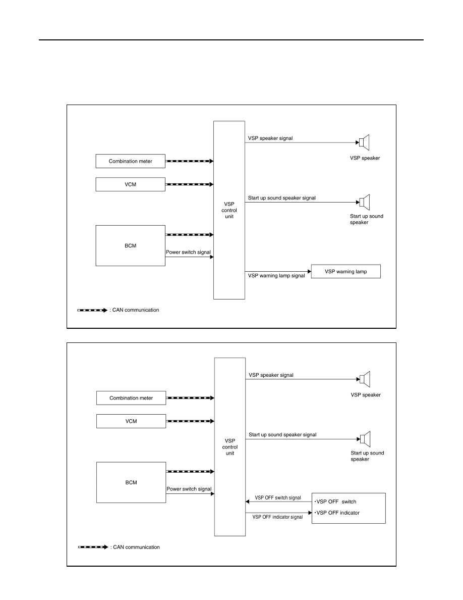
SYSTEM DIAGRAM

Except for Mexico

For Mexico

JSMIA1293GB

JSMIA1313GB

SYSTEM

VSP-13

< SYSTEM DESCRIPTION >

C

D

E

F

G

H

I

J

K

M

A

B

VSP

N

O

P

SYSTEM DESCRIPTION

VSP Control Unit Input Signal (CAN Communication)

Description

• The VSP control unit receives necessary signals from each unit and switch to control the following functions.

- VSP system

- Start up sound system

- Charge sound system

• The VSP control unit can be diagnosed with CONSULT.

START UP SOUND SYSTEM
START UP SOUND SYSTEM : System Description

INFOID:0000000010121567

SYSTEM DIAGRAM

SYSTEM DESCRIPTION

• The start up sound is a function that produces a sound that is linked with the power switch operation and

with the READY to drive indicator lamp on the combination meter.

• The start up sound consists of the following two types.

- The power switch operation sound, which operates when the power switch is operated. 

- The READY effect sound, which is linked with the READY to drive indicator lamp on the combination meter. 

• Four sound types (including OFF) can be selected for the start up sound. 

• The type of start up sound can be set in the combination meter. 

POWER SWITCH OPERATION SOUND

The power switch operation sound is a function that operates when the power switch is pressed.

Operation Description

• The VSP control unit judges power switch operation according to the power switch signal from the BCM. 

• When the power switch signal is received, the VSP control unit transmits the start up sound speaker signal

to the start up sound speaker. 

Operation Condition

When the following conditions are met, the power switch operation sound operates.

Transmit unit

Signal name

Combination meter

Vehicle speed signal

Sound set request signal

Sound signal

VCM

READY to drive indicator lamp request signal

Charge sound request signal

Shift position signal

BCM

Stop lamp switch signal

JSMIA1295GB

Operation condition

Start up sound setting

Other than OFF

Power switch

When pressed

VSP-14

< SYSTEM DESCRIPTION >

SYSTEM

NOTE:

If the power switch is pressed and released quickly, the power switch operation sound may not sound linked

with the switch. 

Operation Stop Condition

When any of the following conditions is met, the power switch operation sound stops. 

Signal Path

• The VSP control unit judges that the power switch operation sound is necessary according to the following

signal, and operates the power switch operation sound. 

• When the VSP control unit judges that the power switch operation sound is necessary, it transmits the fol-

lowing signal. 

Timing Chart

READY EFFECT SOUND

The READY effect sound is a function that operates linked with the READY to drive indicator lamp on the com-

bination meter. 

Operation Description

• The VCM transmits the READY to drive indicator lamp request signal to the VSP control unit via CAN com-

munication. 

Operation stop condition

The operation time of the power switch operation sound ends. 

The conditions for operation of the READY effect sound are 
met. 

The conditions for operation of the VSP system are met. 

Signal name

Signal path

Power switch signal

Power switch 

 BCM 

 VSP control unit

Signal name

Signal path

Start up sound speaker signal

VSP control unit 

 Start up sound speaker

JSMIA0478GB

No.

Description

The power switch operation sound operates when the power switch is pressed. 

The operation time of the power switch operation sound ends. 

When the VSP system operates, operation of the power switch operation sound stops.

SYSTEM

VSP-15

< SYSTEM DESCRIPTION >

C

D

E

F

G

H

I

J

K

M

A

B

VSP

N

O

P

• The VSP control unit judges that the READY effect sound is necessary according to the READY to drive

indicator lamp request signal from the VCM. 

• When the READY to drive indicator lamp request signal is received, the VSP control unit transmits the start

up sound speaker signal to the start up sound speaker. 

Operation Condition

The READY effect sound operates when all of the following conditions are met. 

Operation Stop Condition

The READY effect sound operation stops when any of the following conditions is met. 

Signal Path

• The VSP control unit judges that the READY effect sound is necessary according to the following signal, and

operates the READY effect sound. 

• When the VSP control unit judges that the READY effect sound is necessary, it transmits the following sig-

nal. 

Timing Chart

Operation condition

Start up sound setting

Other than OFF

READY to drive indicator lamp

OFF 

→ ON

Operation stop condition

The operation time for the READY effect sound ends. 

READY to drive indicator lamp

OFF

Power switch

OFF

VSP system

Operates

Signal name

Signal path

Power switch signal

Power switch 

 BCM 

 VSP control unit

READY to drive indicator lamp request signal

VCM 

 VSP control unit

Signal name

Signal path

Start up sound speaker signal

VSP control unit 

 Start up sound speaker

JSMIA0479GB


Content   ..  1246  1247  1248  1249   ..