Content .. 1241 1242 1243 1244 ..
Nissan Leaf. Manual - part 1243
NORMAL CHARGE PORT
VC-139
< REMOVAL AND INSTALLATION >
D
E
F
G
H
I
J
K
L
M
A
B
VC
N
O
P
8. Pull out the normal charge port toward the rear of the vehicle.
WARNING:
Be sure to put on insulating protective gear before beginning work on the high voltage sys-
tem.
9. Remove the PDM (Power Delivery Module) before removing the normal charge port.
WARNING:
Be sure to put on insulating protective gear before beginning work on the high voltage sys-
tem.
INSTALLATION
Install in the reverse order of removal.
WARNING:
Be sure to put on insulating protective gear before beginning work on the high voltage system.
CAUTION:
Be sure to reinstall high-voltage harness clips in their original positions. If a clip is damaged, replace it
with a new clip before installing.
Disassembly and Assembly
INFOID:0000000010121301
DISASSEMBLY
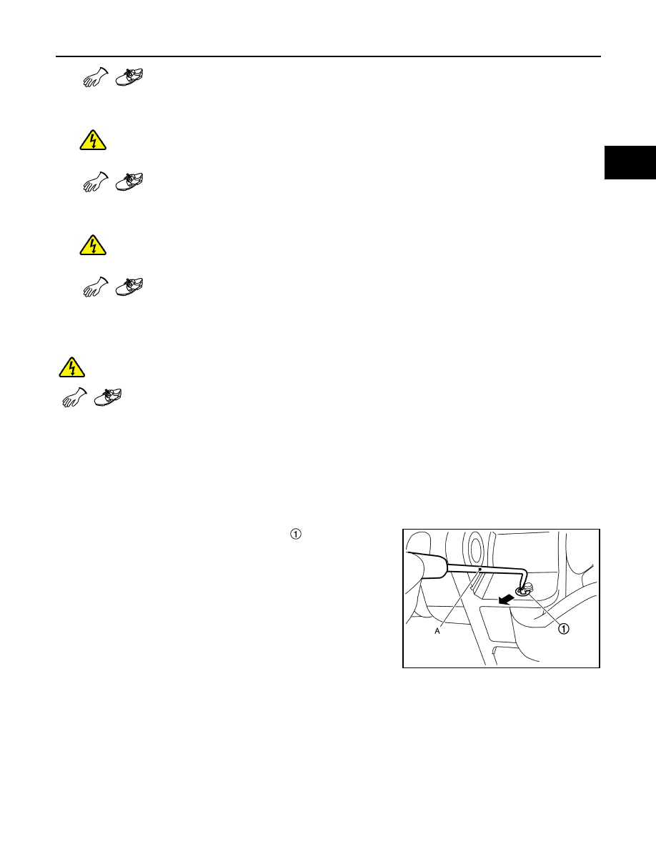
Cover Side
1. Use a suitable tool (A) to remove the clip that is attached to
the pin.
JSCIA0219ZZ