Nissan Leaf. Manual - part 1238


  Index      Nissan     Nissan Leaf (2011-2014 year) - Service and Repair Manual


Search            


Content   ..  1236  1237  1238  1239   ..


Nissan Leaf. Manual - part 1238


PDM(POWER DELIVERY MODULE)

VC-119

< REMOVAL AND INSTALLATION >

D

E

F

G

H

I

J

K

L

M

A

B

VC

N

O

P

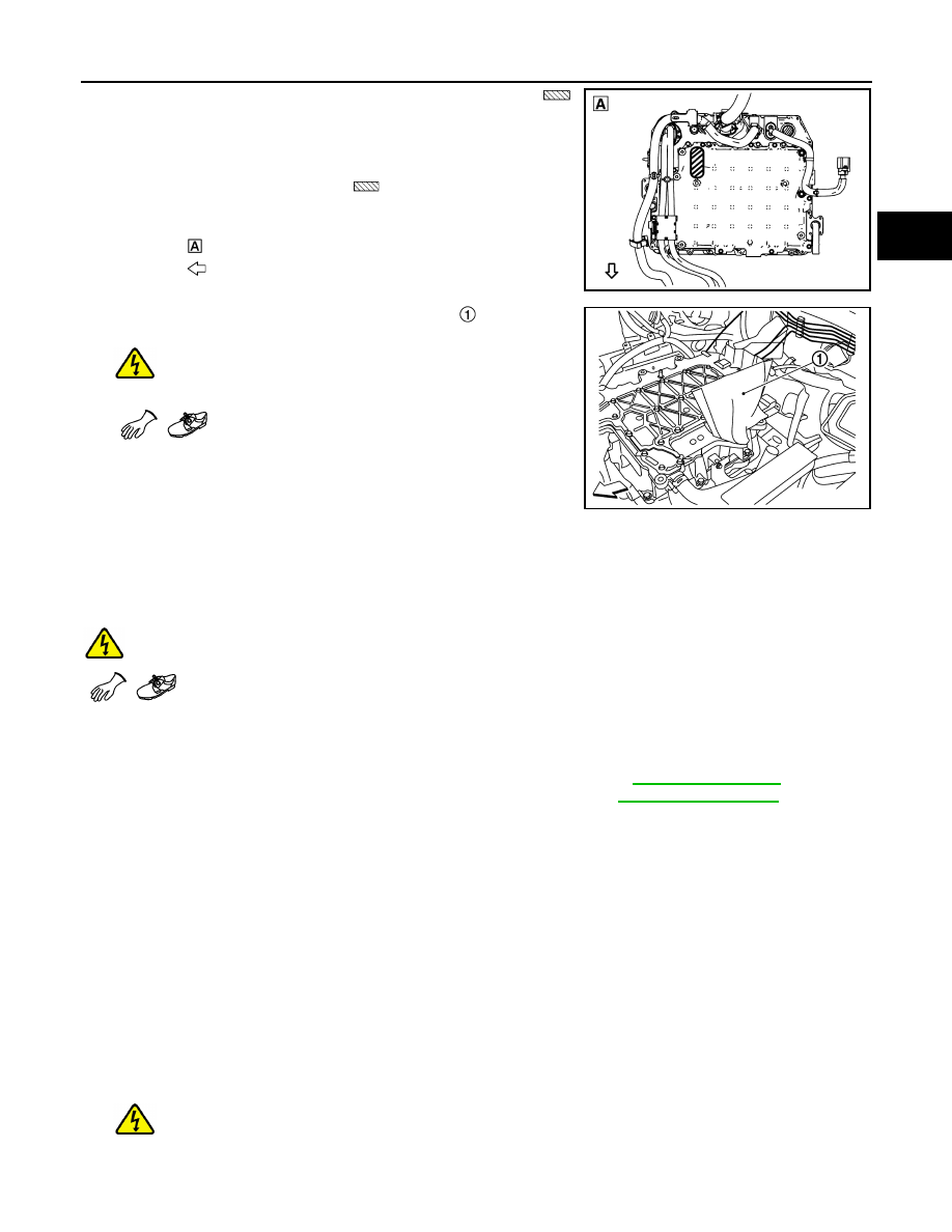
• Never place it in the opening area (shaded area 

)

located at the back of PDM (Power Delivery Module).

Place it on other area such as a place of wood.

• To prevent the intrusion of foreign matter such as dust

and dirt into PDM (Power Delivery Module), cover the
opening area (shaded area 

) located at the back of

PDM (Power Delivery Module) with a tape.

24. Cover the high-voltage bus bar with shop paper  .

WARNING:

Be sure to put on insulating protective gear before

beginning work on the high voltage system.

CAUTION:

Be sure to protect the high-voltage bus bar with clean shop

paper so that dust, dirt, and other substances do not enter

the driver motor. If the high-voltage bus bar is touched or if

the high-voltage bus bar is dirty, clean it using ethanol.

INSTALLATION

Note the following items and install in the reverse order of removal.

WARNING:

Be sure to put on insulating protective gear before beginning work on the high voltage system.

CAUTION:

• Be sure to reinstall high voltage harness clips in their original positions. If a clip is damaged, replace

it with a new clip before installing.

• Be sure to perform correct air bleeding after adding coolant. Refer to 

HCO-12, "Refilling"

.

• After all parts are installed, be sure to check equipotential. Refer to 

VC-125, "Inspection"

.

Disassembly and Assembly

INFOID:0000000010121294

DISASSEMBLY

CAUTION:

• Always prepare a protective cover [servive parts number: 291X2 3NF0A] before checking/replacing

the following parts that the cover of PDM (Power Delivery Module) is required to be opened.

- PDM (Power Delivery Module)

- Quick charge port

- Normal charge port

- Electric compressor harness

- Li-ion battery high-voltage harness
1. In order to prevent dust or other substances on the PDM (Power Delivery Module) cover from entering into

the PDM (Power Delivery Module), wipe away any dirt from the PDM (Power Delivery Module) cover

using dry shop cloth or similar material.

WARNING:

Be sure to put on insulating protective gear before beginning work on the high voltage sys-

tem.

: Back of PDM (Power Delivery Module)

: Front of PDM (Power Delivery Module)

JPCIA0469ZZ

JPCIA0333ZZ

VC-120

< REMOVAL AND INSTALLATION >

PDM(POWER DELIVERY MODULE)

2. Remove the PDM (Power Delivery Module) cover mounting

bolts in the order from16 to 3 as shown in the figure.

WARNING:

Be sure to put on insulating protective gear before

beginning work on the high voltage system.

3. Use a flathead screwdriver, pawl, or similar tool to pry open a

part of the PDM (Power Delivery Module) cover and cut away

the liquid gasket.

WARNING:

Be sure to put on insulating protective gear before

beginning work on the high voltage system.

CAUTION:

Wrap the flathead screwdriver with tape or shop cloth when

working to avoid scratching the mounting surface.

NOTE:

If the gasket is difficult to separate, use a remover (A) to create

clearance while cutting away the liquid gasket.

4. Wear anti-static gloves and remove the PDM (Power Delivery

Module) cover by lifting first the rear then the front as shown in

the figure.

WARNING:

Be sure to put on insulating protective gear before

beginning work on the high voltage system.

CAUTION:

Anti-static gloves must be worn for all subsequent steps.

CAUTION:

: Vehicle front

JPCIA0309ZZ

JPCIA0310ZZ

JPCIA0311ZZ

JPCIA0312ZZ

PDM(POWER DELIVERY MODULE)

VC-121

< REMOVAL AND INSTALLATION >

D

E

F

G

H

I

J

K

L

M

A

B

VC

N

O

P

When lifting up the PDM (Power Delivery Module) cover, be
careful not to contact the circuit board  .

5. Install a protective cover   [service parts number: 291X2

3NF0A].

WARNING:

Be sure to put on insulating protective gear before

beginning work on the high voltage system.

CAUTION:

• In order to prevent entry of dust or dirt into the circuit

board section, install the protective cover immediately

after removing the PDM (Power Delivery Module) cover.

6. Remove the mounting bolt and screw from each high-voltage terminal, then remove the high-voltage ter-

minals from the PDM (Power Delivery Module).

• Removing the quick charge port

WARNING:

Be sure to put on insulating protective gear before beginning work on the high voltage sys-

tem.

JPCIA0313ZZ

JPCIA0314ZZ

JPCIA0352ZZ

VC-122

< REMOVAL AND INSTALLATION >

PDM(POWER DELIVERY MODULE)

• Removing the Li-ion battery high-voltage harness

• Removing the normal charge port

• Removing the electric compressor harness

ASSEMBLY

1. Install each of the high-voltage harnesses.
2. Use an acrylic scraper [SST: KV10120900 (J-51053)] and remove the old liquid gasket from the mounting

surface.

WARNING:

Be sure to put on insulating protective gear before beginning work on the high voltage sys-

tem.

JPCIA0353ZZ

JPCIA0354ZZ

JPCIA0355ZZ


Content   ..  1236  1237  1238  1239   ..