Content .. 1189 1190 1191 1192 ..
Nissan Leaf. Manual - part 1191
P0A2D DRIVE MOTOR A TEMP SENSOR
TMS-45
< DTC/CIRCUIT DIAGNOSIS >
D
E
F
G
H
I
J
K
L
M
A
B
TMS
N
O
P
NO
>> Repair or replace damaged parts.
4.
CHECK TRACTION MOTOR TEMPERATURE SENSOR CIRCUIT
1. Disconnect the traction motor harness connector.
2. Check the resistance between traction motor inverter vehicle side harness connector terminals and trac-
tion motor vehicle side harness connector terminals.
3. Check the harness for short.
Is the inspection result normal?
YES
>> GO TO 5.
NO
>> Repair or replace damaged parts.
5.
CHECK TRACTION MOTOR TEMPERATURE SENSOR
Check the traction motor temperature sensor. Refer to
TMS-45, "Component Inspection (Traction Motor Tem-
.
Is the inspection result normal?
YES
>> Replace the traction motor inverter. Refer to
TMS-103, "Removal and Installation"
.
NO
>> Replace the traction motor. Refer to
TMS-109, "Removal and Installation"
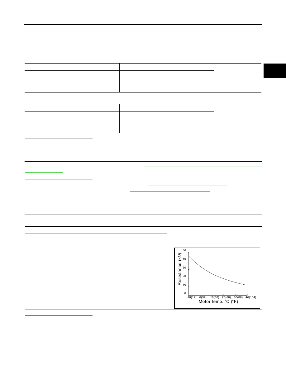
Component Inspection (Traction Motor Temperature Sensor)
INFOID:0000000010120929
1.
CHECK TRACTION MOTOR TEMPERATURE SENSOR
Check the resistance between traction motor connector terminals.
Is the inspection result normal?
YES
>> INSPECTION END
NO
>> Replace the traction motor due to malfunction in the traction motor temperature sensor. Refer to
TMS-109, "Removal and Installation"
.
Traction motor inverter
Traction motor
Resistance
Connector
Terminal
Connector
Terminal
F13
44
F14
4
1
Ω or less
45
3
Traction motor inverter
Traction motor
Resistance
Connector
Terminal
Connector
Terminal
F13
44
F14
3
100 k
Ω or more
45
4
Traction motor connector
Resistance
Terminal
3
4
Within
± 50% of temperature characteristics diagram
JPCIA0030GB