Content .. 1188 1189 1190 1191 ..
Nissan Leaf. Manual - part 1190
P0A1B DRIVE MOTOR A CONTROL MODULE
TMS-41
< DTC/CIRCUIT DIAGNOSIS >
D
E
F
G
H
I
J
K
L
M
A
B
TMS
N
O
P
DTC/CIRCUIT DIAGNOSIS
P0A1B DRIVE MOTOR A CONTROL MODULE
DTC Logic
INFOID:0000000010120922
DTC DETECTION LOGIC
DTC CONFIRMATION PROCEDURE
1.
PRECONDITIONING
If “DTC CONFIRMATION PROCEDURE” has been previously conducted, always power switch OFF and wait
at least 10 seconds before conducting the next test.
>> GO TO 2.
2.
CHECK DTC DETECTION
With CONSULT
1. Power switch ON and wait for 10 seconds or more.
2. Check DTC.
Is “P0A1B” detected?
YES
>> Go to
.
NO-1 >> To check malfunction symptom before repair: Refer to
GI-53, "Intermittent Incident"
NO-2 >> Confirmation after repair: INSPECTION END
Diagnosis Procedure
INFOID:0000000010120923
1.
REPLACE TRACTION MOTOR INVERTER
Replace the traction motor inverter. Refer to
TMS-103, "Removal and Installation"
.
>> END
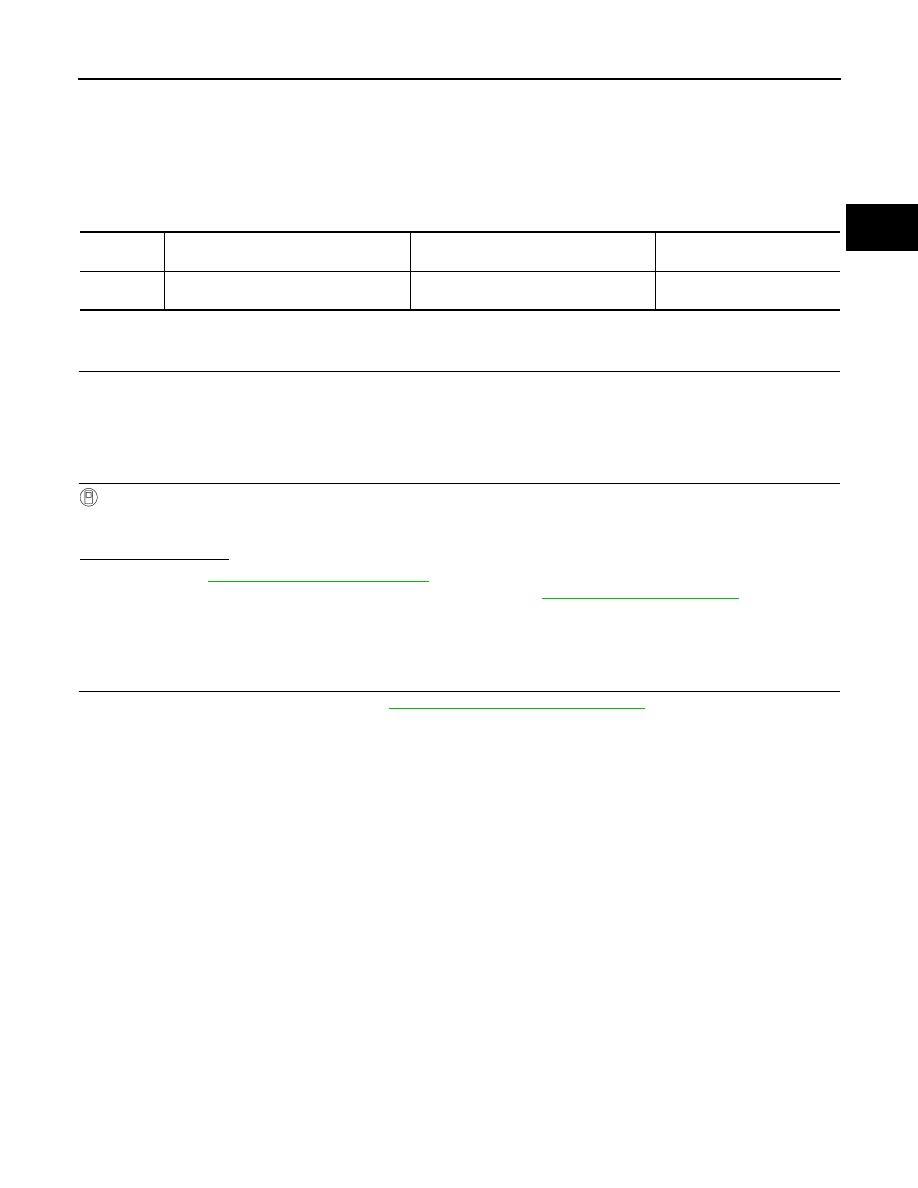
DTC
CONSULT screen terms
(Trouble diagnosis content)
Malfunction detected condition
Possible cause
P0A1B
DRIVE MOTOR A CONTROL MODULE
(Drive Motor “A” Control Module)
A malfunction is detected in the traction
motor inverter (motor controller)
Traction motor inverter