Content .. 1167 1168 1169 1170 ..
Nissan Leaf. Manual - part 1169
TM-82
< DTC/CIRCUIT DIAGNOSIS >
[ELECTRIC SHIFT]
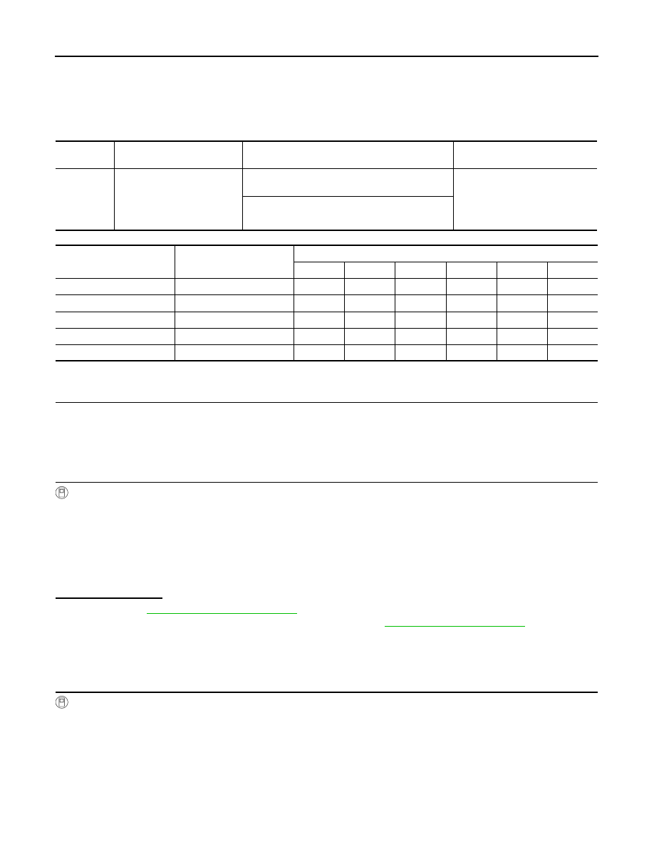
P1896 SHIFT POWER SUPPLY
P1896 SHIFT POWER SUPPLY
DTC Logic
INFOID:0000000010119593
DTC DETECTION LOGIC
Position Pattern Table
DTC CONFIRMATION PROCEDURE
1.
PREPARATION BEFORE WORK
If another "DTC CONFIRMATION PROCEDURE" occurs just before, power switch OFF and wait for at least
10 seconds, then perform the next test.
>> GO TO 2.
2.
PERFORM DTC CONFIRMATION PROCEDURE
With CONSULT
1. Set the vehicle to READY.
2. Select “Data Monitor” in “SHIFT”.
3. Select “RANGE POSITION”.
4. Shift the selector lever as follows. (Hold the selector lever at each position for 2 seconds or more.)
-
H
→ N → R → N → D → N → H
5. Repeat step 4 five times.
6. Check DTC.
Is “P1896” detected?
YES
>> Go to
NO-1 >> To check malfunction symptom before repair: Refer to
GI-53, "Intermittent Incident"
.
NO-2 >> Confirmation after repair: INSPECTION END
Diagnosis Procedure
INFOID:0000000010119594
1.
CHECK ELECTRIC SHIFT SENSOR INPUT SIGNAL
With CONSULT
1. Set the vehicle to READY.
2. Select “Data Monitor” in “SHIFT”.
3. Select “SHIFT SENSOR 1”, “SHIFT SENSOR 2”, “SHIFT SENSOR 3”, “SHIFT SENSOR 4”, “SHIFT SEN-
SOR 5”, and “SHIFT SENSOR 6”.
4. Operate the selector lever to identify a electric shift sensor of which value does not change.
DTC
CONSULT screen terms
(Trouble diagnosis content)
DTC detection condition
Possible cause
P1896
SHIFT POWER SUPPLY
(Electric Shift Sensor Power
Supply)
It is detected that electric shift sensors No. 1, 3, and
5 are stuck at OFF.
• Electric shift sensor
• Electric shift control module
• Harness or connectors
(Each circuit is open or short-
ed.)
It is detected that electric shift sensors No. 2, 4, and
6 are stuck at OFF.
Electric shift control module
recognition position
Selector lever position
Electric shift sensor
No. 1
No. 2
No. 3
No. 4
No. 5
No. 6
H
H
OFF
OFF
ON
OFF
OFF
ON
P
H
OFF
OFF
ON
OFF
OFF
ON
R
R
ON
ON
OFF
OFF
OFF
OFF
N
N
OFF
ON
ON
ON
OFF
OFF
D
D
OFF
OFF
OFF
ON
ON
OFF