Content .. 1044 1045 1046 1047 ..
Nissan Leaf. Manual - part 1046
COMPONENT PARTS
SB-9
< SYSTEM DESCRIPTION >
C
D
E
F
G
I
J
K
L
M
A
B
SB
N
O
P
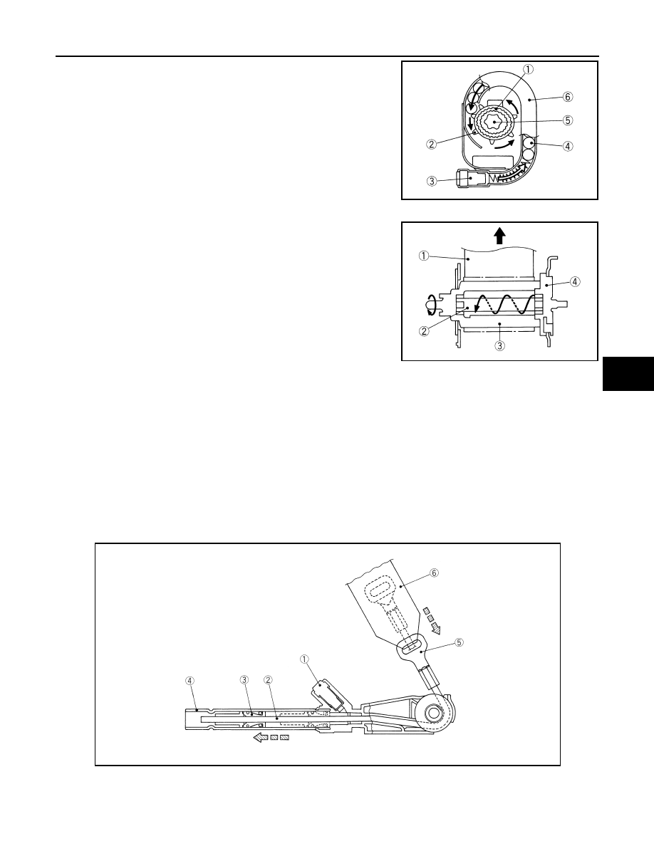
• In a frontal collision that exceeds the specified limit, air bag sensor
unit detects the collision, transmits an electrical signal to gas gen-
erator (3) in manifold case, and activates gas generator. Gas is
generated.
• The pressure of the generated gas moves the ball (4) inside of
pipe (6). The ball then presses ring gear (2) which is engaged to
the pinion gear (1).
• The rotation of the ring gear rotates the shaft (5) in the retracting
direction of the seat belt. Seat belt is retracted.
LOAD LIMITER (ELR) MECHANISM
• In a collision, when ELR shaft (2) is locked, a load caused by
impact is applied to webbing (1)
• When a load is continuously applied to webbing and reaches or
exceeds the specified level, a rotating force is applied to ELR shaft
that is engaged to lock portion (4) and bobbin (3). ELR shaft twists.
• As ELR shaft is twisted, webbing is pulled out while keeping a cer-
tain level of tension and easing the impact to the chest of front seat
passenger.
Double pre-tensioner seat belt
INFOID:0000000010119332
DESCRIPTION
The system combines lap pre-tensioner mechanism for lumbar seat belt and pre-tensioner seat belt with load
limiter. The system upgrades passenger restraint by reducing lumbar movement during a frontal collision.
LAP PRE-TENSIONER MECHANISM
• In a frontal collision that exceeds the specified limit, air bag sensor unit detects the collision, transmits an
electrical signal to gas generator (1) in pipe, and activates gas generator. Gas is generated. The pressure of
the generated gas moves the piston inside of pipe toward pipe front direction, and retracts wire.
• Lap anchor is installed to end of the wire and end of seat belt is connected to lap anchor. The wire therefore
retracts seat belt.
• When piston stops, clutch mechanism integrated to piston prevents piston from moving in the original direc-
tion. Wire and lap anchor therefore remain in the retracted status.
JMHIA0168ZZ
JMHIA0169ZZ
1.
Gas generator
2.
Wire
3.
Piston
4.
Pipe
5.
Lap anchor
6.
Seat belt
PHIA1226J