Index Nissan Nissan Leaf (2011-2014 year) - Service and Repair Manual
Search
Content .. 1007 1008 1009 1010 ..
Nissan Leaf. Manual - part 1009
PG-48
< WIRING DIAGRAM >
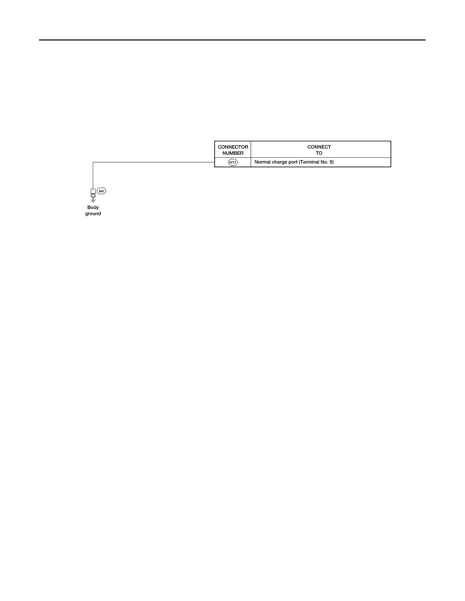
GROUND
HIGH VOLTAGE HARNESS
AAMIA2474GB